

 Download PDF
DH60-18A IXYS
Document overview
- PDF pages: 2
Technical content
Page 1
Fast Recovery Diode
SONIC-FRDTM series
VRSM VRRM
Type
V V
1400 1400
DH 60-14A
1600 1600
DH 60-16A
1800 1800
DH 60-18A
Symbol
Conditions
IFRMS
TVJ = TVJM
IFAVM
TC = 89°C; rectangular, d = 0.5
IFRM
tP < 10 µs; rep. rating, pulse width limited by TVJM
IFSM
TVJ = 45°C; tp = 10 ms (50 Hz), sine
EAS
TVJ = 25°C; non-repetitive IAS = tbd A; L = 100 µH
IAR
VA = 1.5·VR typ.; f = 10 kHz; repetitive
TVJ
TVJM
Tstg
Ptot
TC = 25°C
Md
Mounting torque
Weight
Symbol
Conditions
DH 60
IFAVM = 60 A
VRRM = 1400-1800 V
= 150 ns trr
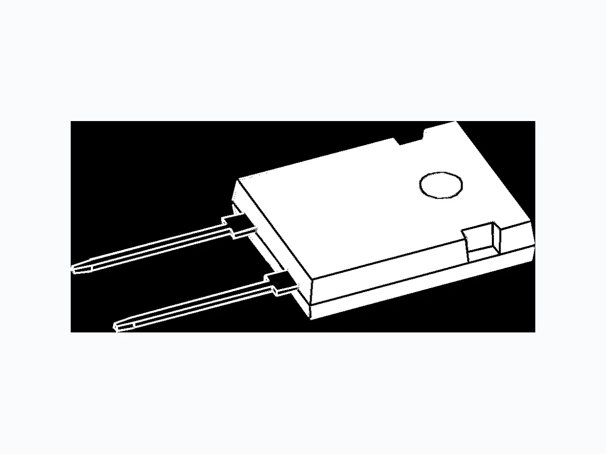
TO-247 AD
C
A
C A
C
A = Anode, C = Cathode
Features
Maximum Ratings
- Small temperature dependence for
100
A - forward voltage drop - reverse recovery current
60
A
- Optimized for
900
A - dynamic avalanche ruggedness - low loss performance
650
A
- Exceptionally soft recovery
- Low reverse recovery current characteristic
tbd
mJ
- Soft recovery current without tail
- Optimized for high frequency hard switching
tbd
A
Applications
- Antiparallel diode for high frequency
-40...+150
°C switching devices
150
°C
- Anti saturation diode
-40...+150
°C
- Snubber diode
- Free wheeling diode in converters
415
W and motor control circuits
- Rectifiers in switch mode power
0.8...1.2
Nm supplies (SMPS)
- Induction heating and melting
6
g
- Uninterruptible power supplies (UPS)
- Ultrasonic cleaners and welders
Characteristic Values
| typ. | max. |
|---|---|
| I T = 25°C V = V 100 R VJ R RRM T = 125°C V = V 2 VJ R RRM | 200 µA mA |
| V I = 60 A; T = 125°C F F VJ T = 25°C 2.3 VJ | 2.7 V 2.7 V |
| V For power-loss calculations only T0 r T = T T VJ VJM | 1.95 V 12 mΩ |
| R thJC R 0.25 thCH | 0.3 K/W K/W |
| t I = 60 A; -di/dt = 600 A/µs; V = 1200 V; 150 rr F R I T = 25°C 50 RM VJ | ns A |
| t I = 60 A; -di/dt = 600 A/µs; V = 1200 V; 350 rr F R I T = 125°C 55 RM VJ | ns A |
Dimensions
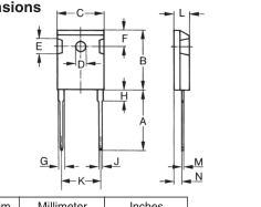
| Dim. | Millimeter Min. Max. | Inches Min. Max. |
|---|---|---|
| A B | 19.81 20.32 20.80 21.46 | 0.780 0.800 0.819 0.845 |
| C D* | 15.75 16.26 3.55 3.65 | 0.610 0.640 0.140 0.144 |
| E F | 4.32 5.49 5.4 6.2 | 0.170 0.216 0.212 0.244 |
| G H | 1.65 2.13 - 4.5 | 0.065 0.084 - 0.177 |
| J K | 1.0 1.4 10.8 11.0 | 0.040 0.055 0.426 0.433 |
| L M | 4.7 5.3 0.4 0.8 | 0.185 0.209 0.016 0.031 |
| N | 1.5 2.49 | 0.087 0.102 |
Data according to IEC 60747
IXYS reserves the right to change limits, test conditions and dimensions
1 - 2
© 2004 IXYS All rights reserved
Page 2
DH 60
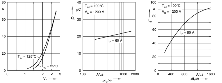
IF
Fig. 2 Typ. reverse recovery charge
Fig. 1 Typ. forward current
Fig. 3 Typ. peak reverse current
Qr versus -diF/dt
IF versus VF
IRM versus -diF/dt
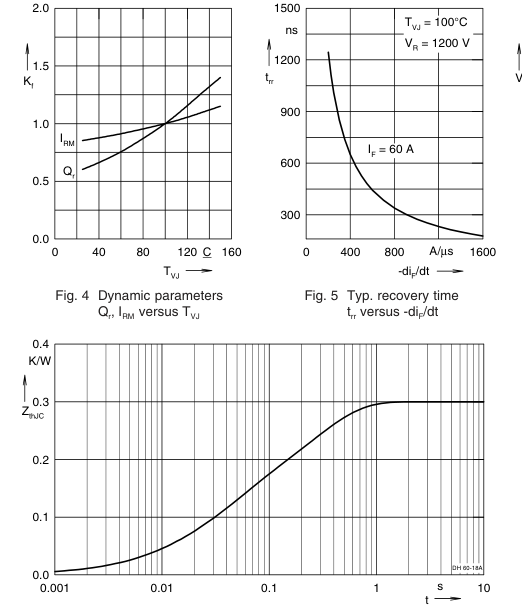
Fig. 7 Transient thermal resistance junction to case
IXYS reserves the right to change limits, test conditions and dimensions
© 2004 IXYS All rights reserved
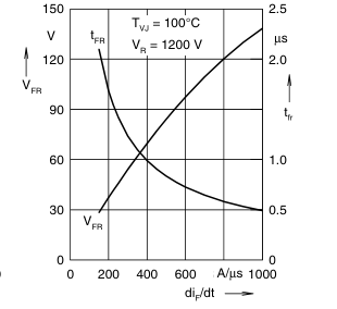
Fig. 6 Typ. peak forward voltage VFR and tfr versus diF/dt
NOTE: Fig. 2 to Fig. 6 shows typical values
2 - 2