
CG2 VISHAY
Document overview
- Manufacturer or author: Provided By www.digicamel.com(free datasheet download site)
- PDF pages: 4
Technical content
Features
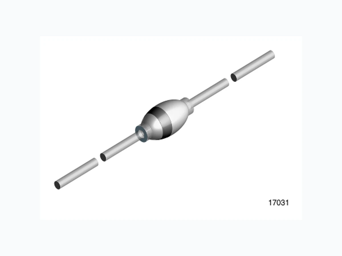
- Specially designed for clamping circuits, horizon- tal deflection systems and damper applications High temperature metallurgically bonded con- struction Cavity-free glass passivated junction 2.0 ampere operation at T amb = 50 °C with no ther- mal runaway Hermetically sealed package Mechanical Data Case: DO-204AP Sintered glass case Terminals: Solder plated axial leads, solderable per MILSTD- 750, Method 2026 Polarity: Color band denotes cathode end Mounting Position: Any Weight: approx. 560 mg Parts Table Absolute Maximum Ratings Tamb = 25 °C, unless otherwise specified Maximum Thermal Resistance Tamb = 25 °C, unless otherwise specified Part Type differentiation Package CG2 V RRM = 1400 V DO-204AP(G-1) DG2 V RRM = 1500 V DO-204AP(G-1) Parameter Test condition Part Symbol Value Unit Reverse voltage = Repetitive peak reverse voltage see electrical characteristics CG2 V R = VRRM 1400 V DG2 V R = VRRM 1500 V Maximum average forward rectified current 0.375 " (9.5 mm) lead length at Tamb = 50 °C IF(AV) 2.0 A Peak forward surge current 8.3 ms single half sine wave superimposed on rated load (JEDEC Method) IFSM 40 A Maximum full load reverse current full cycle average 0.375 " (9.5 mm) lead length at Tamb =100 °C IR(AV) 200 µA Operating junction and storage temperature range TJ, TSTG - 55 to + 175 °C Parameter Test condition Symbol Value Unit Typical thermal resistance 1) RθJA 55 K/W
Figure 5. Typical Junction Capacitance
www.vishay.com Document Number 86082 Rev. 1.3, 11-Aug-04 VISHA YCG2 / DG2 Vishay Semiconductors Ozone Depleting Substances Policy Statement It is the policy of Vishay Semiconductor GmbH to 1. Meet all present and future national and international statutory requirements. 2. Regularly and continuously improve the performance of our products, processes, distribution and operatingsystems with respect to their impact on the health and safety of our employees and the public, as well as their impact on the environment. It is particular concern to control or eliminate releases of those substances into the atmosphere which are known as ozone depleting substances (ODSs). The Montreal Protocol (1987) and its London Amendments (1990) intend to severely restrict the use of ODSs and forbid their use within the next ten years. Various national and international initiatives are pressing for an earlier ban on these substances. Vishay Semiconductor GmbH has been able to use its policy of continuous improvements to eliminate the use of ODSs listed in the following documents. 1. Annex A, B and list of transitional substances of the Montreal Protocol and the London Amendments respectively 2. Class I and II ozone depleting substances in the Clean Air Act Amendments of 1990 by the Environmental Protection Agency (EPA) in the USA 3. Council Decision 88/540/EEC and 91/690/EEC Annex A, B and C (transitional substances) respectively. Vishay Semiconductor GmbH can certify that our semiconductors are not manufactured with ozone depleting substances and do not contain such substances. We reserve the right to make changes to improve technical design and may do so without further notice. Parameters can vary in different applications. All operating parameters must be validated for each customer application by the customer. Should the buyer use Vishay Semiconductors products for any unintended or unauthorized application, the buyer shall indemnify Vishay Semiconductors against all claims, costs, damages, and expenses, arising out of, directly or indirectly, any claim of personal damage, injury or death associated with such unintended or unauthorized use. Vishay Semiconductor GmbH, P.O.B. 3535, D-74025 Heilbronn, Germany Telephone: 49 (0)7131 67 2831, Fax number: 49 (0)7131 67 2423