
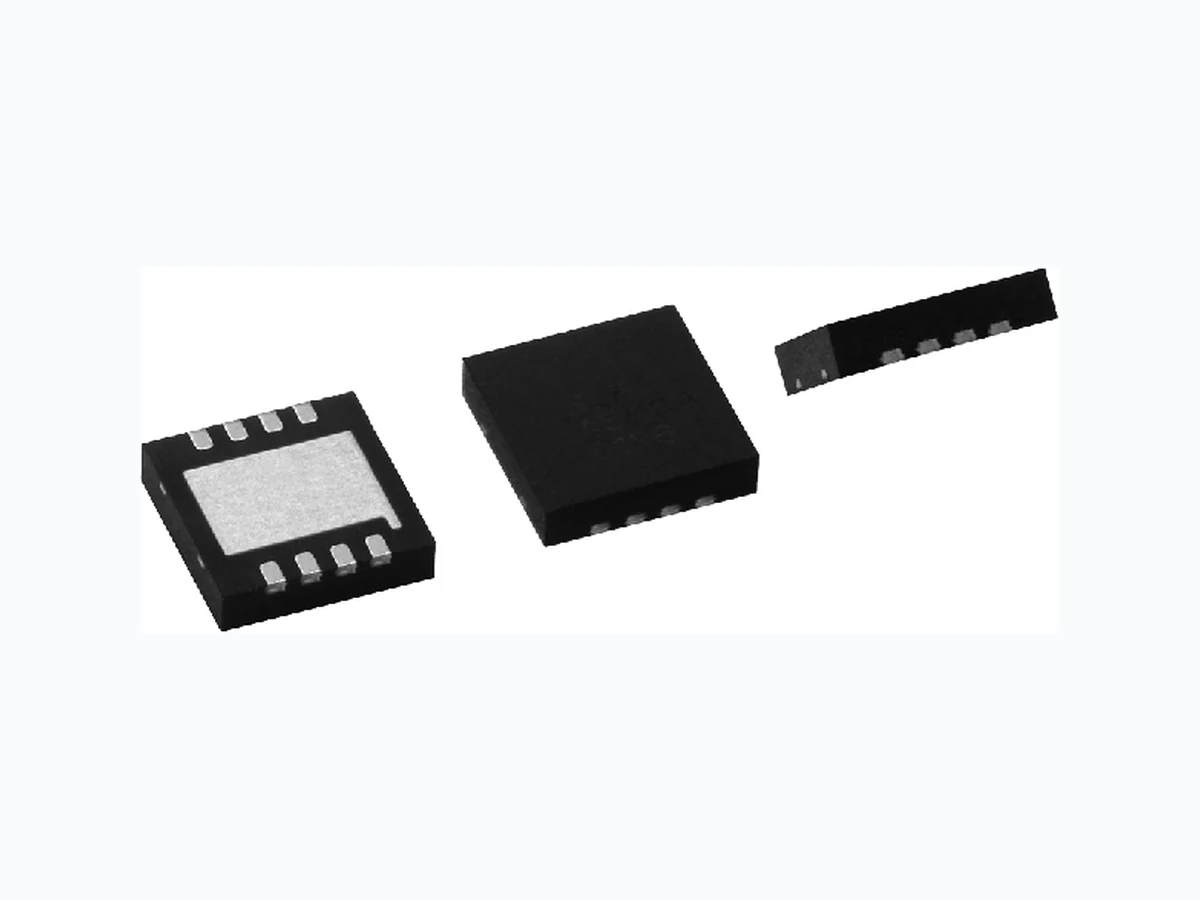
DFN VISHAY
Document overview
- Manufacturer or author: Provided By www.digicamel.com(FREE DATASHEET DOWNLOAD SITE)
- PDF pages: 3
Technical content
www.vishay.com Vishay Dale Thin Film Revision: 28-May-15 1 Document Number: 60109 For technical questions, contact: thinfilm@vishay.com THIS DOCUMENT IS SUBJECT TO CHANGE WITHOUT NOTICE. THE PRODUCTS DESCRIBED HEREIN AND THIS DOCUMENT ARE SUBJECT TO SPECIFIC DISCLAIMERS, SET FORTH AT www.vishay.com/doc?91000 Dual Flat No Lead Molded Precision Thin Film Resistor Surface Mount Network The DFN series of precision surface mount resistor networks feature isolated thin film precision resistors mounted in a 0.8 mm pitch 4 mm x 4 mm dual flat no lead package. The networks feature 50 % savings in board space over traditional SOIC packages. Th ey are ideally suited for applications of unity gain operational amplifiers that require close TC tracking and tigh t ratio tolerances over temperature. Custom configurations are available upon request. SCHEMATIC
FEATURES
- 0.8 mm lead pitch
- MSL level 1 per J-STD-020
- Low profile 1 mm seated height
- Small size 4 mm x 4 mm size 50 % board savings over SOIC packages
- Wide resistance range 100 to 100 k available
- Custom configurations available
- Low TCR ± 25 ppm, TCR tracking to ± 3 ppm
- Ratio tolerances to ± 0.025 %
- Material categorization: fo r definitions of compliance please see www.vishay.com/doc?99912 TYPICAL PERFORMANCE Note
- Consult factory for additional R values and schematics R1R1R1 ABSOLUTE TRACKING TCR 25 3 ABSOLUTE RATIO TOL. 0.1 0.05 STANDARD RESISTANCE OFFERING (R1 =) 500 10 k 1 k 20 k 2 k 50 k 4.99 k 100 k 5 k STANDARD ELECTRICAL SPECIFICATIONS TEST SPECIFICATIONS CONDITIONS Material Passivated nichrome - Pin/Lead Number 8- Resistance Range 100 to 100 k per resistor - TCR: Absolute ± 25 ppm/°C -55 °C to +125 °C TCR: Tracking ± 3 ppm/°C -55 °C to +125 °C Tolerance: Absolute ± 0.05 % to ± 1.0 % +25 °C Tolerance: Ratio ± 0.025 % to ± 0.5 % +25 °C Power Rating: Resistor 100 mW Maximum at +70 °C Power Rating: Package 100 mW x number of resistors Maximum at +70 °C Stability: Absolute R ± 0.05 % 2000 h at +70 °C Stability: Ratio R ± 0.015 % 2000 h at +70 °C Voltage Coefficient < 0.1 ppm/V - Working Voltage 100 V max. not to exceed - Operating Temperature Range -55 °C to +125 °C - Storage Temperature Range -55 °C to +150 °C - Noise < -30 dB - Thermal EMF < 0.08 μV/°C - Shelf Life Stability: Absolute R ± 0.01 % 1 year at +25 °C Shelf Life Stability: Ratio R ± 0.002 % 1 year at +25 °C P x R
www.vishay.com Vishay Dale Thin Film Revision: 28-May-15 2 Document Number: 60109 For technical questions, contact: thinfilm@vishay.com THIS DOCUMENT IS SUBJECT TO CHANGE WITHOUT NOTICE. THE PRODUCTS DESCRIBED HEREIN AND THIS DOCUMENT ARE SUBJECT TO SPECIFIC DISCLAIMERS, SET FORTH AT www.vishay.com/doc?91000 Note
- Contact factory for package outlines for higher pin count or custom configurations Notes (1) Tolerance available on 1 k and up (2) Preferred packaging code DIMENSIONS AND IMPRINTING in millimeters Pin 1 Dot by Marking DFNA XXXX MMYY Resistance Value Code Date Code (MMYY) 4.000 ± 0.050 4.000 ± 0.050 2.700 ± 0.050 Exposed Pad 3.500 ± 0.050 Exposed Pad 2.400 Ref. 0.300 ± 0.050 A 0.000 - 0.050 0.203 Ref. 1234 8765 Pin 1 Indentification Chamfer 0.300 x 45°
0.800 BSC
0.400 ± 0.050 A Max. Nom. Min. 0.900 0.850 0.800 (4 mm x 4 mm) TOP VIEW BOTTOM VIEW SIDE VIEW MECHANICAL SPECIFICATIONS Resistive Element Passivated nichrome Substrate Material Ceramic Body Molded epoxy Terminals Copper alloy Plating 100 % matte tin Marking Resistance to Solvents Per MIL-PRF-914 GLOBAL PART NUMBER INFORMATION New Global Part Numbering: DFNA1002AT1 GLOBAL MODEL SCHEMATIC RESISTANCE TOLERANCE AND RATIO TOLERANCE PACKAGING DFN (Lead (Pb)-free) (e3) A = Isolated equal value resistors The first 3 digits are significant figures and the last digit specifies the number of zeros to follow. Example: 1002 = 10 k 1003 = 100 k 4991 = 4.99 k Z = ± 0.05 % abs. ± 0.025 ratio (1) A = ± 0.1 % abs. ± 0.05 % ratio B = ± 0.1 % abs. ± 0.1 % ratio C = ± 0.25 % abs. ± 0.1 % ratio D = ± 0.5 % abs. ± 0.1 % ratio F = ± 1.0 % abs. ± 0.5 % ratio TAPE AND REEL T0 = 100 min., 100 mult T1 = 1000 min., 1000 mult (2) T3 = 300 min., 300 mult T5 = 500 min., 500 mult TF = Full reel TS = 100 min., 1 mult UF = TUBED A1002ATF ND 1
www.vishay.com Vishay Revision: 13-Jun-16 1 Document Number: 91000 Disclaimer ALL PRODUCT, PRODUCT SPECIFICATIONS AND DATA AR E SUBJECT TO CHANGE WITH OUT NOTICE TO IMPROVE RELIABILITY, FUNCTION OR DESIGN OR OTHERWISE. Vishay Intertechnology, Inc., its affiliates, agents, and employee s, and all persons acting on it s or their behalf (collectivel y, “Vishay”), disclaim any and all liability for any errors, inaccuracies or incompleteness contained in any datasheet or in any other disclosure relating to any product. Vishay makes no warranty, representation or guarantee regarding the suitability of th e products for any particular purpose or the continuing production of any product. To the maximum extent permitted by applicable law, Vishay disclaims (i) any and all liability arising out of the application or use of any product , (ii) any and all liability, including without limitation specia l, consequential or incidental damages, and (iii) any and all implied warranties, includ ing warranties of fitness for particular purpose, non-infringement and merchantability. Statements regarding the suitability of products for certain types of applicatio ns are based on Vishay’s knowledge of typical requirements that are often placed on Vishay products in generic applications. Such statements are not binding statements about the suitability of products for a particular applic ation. It is the customer’s responsibility to validate tha t a particular product with the prope rties described in the product sp ecification is suitable for use in a particular application. Parameters provided in datasheets and / or specifications may vary in different ap plications and performance may vary over time. All operating parameters, including typical parameters, must be validated for each customer application by the customer’s technical experts. Product specifications do not expand or otherwise modify Vishay’s term s and conditions of purchase, including but not limited to the warranty expressed therein. Except as expressly indicated in writing, Vishay products are not designed for use in medical, life-saving, or life-sustaining applications or for any other application in which the failure of the Vishay product could result in personal injury or death. Customers using or selling Vishay product s not expressly indicated for use in such applications do so at their own risk. Please contact authorized Vishay personnel to obtain writ ten terms and conditions rega rding products designed for such applications. No license, express or implied, by estoppel or otherwise, to any intellectual property rights is gran ted by this document or by any conduct of Vishay. Product names and markings noted herein may be trademarks of their respective owners.