
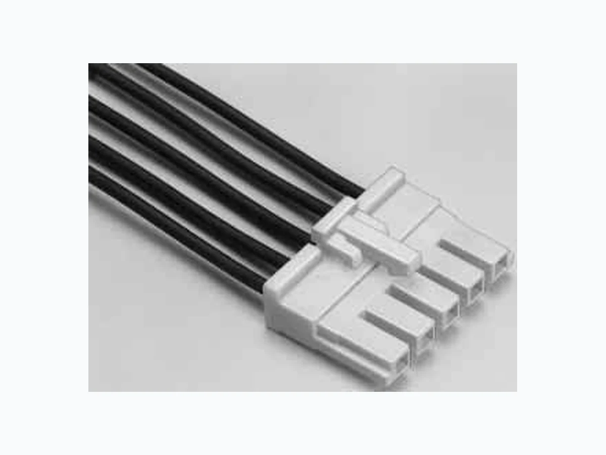

 Download PDF
DF5A-2S-5C_1 HIROSE
Document overview
- PDF pages: 6
Technical content
Page 1
All non-RoHS products have been discontinued, or will be discontinued soon. Please check the products status on the Hirose website RoHS search at www.hirose-connectors.com, or contact your Hirose sales representative.

■Features
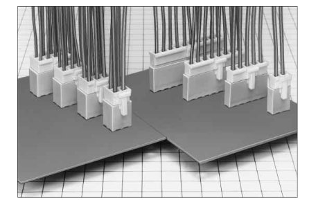
1. Potting Product
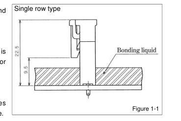
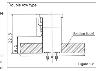
This connector is capable of potting 9mm maximum, and 22.5mm mounting height is a low profile. (Figure 1).
2. Prevent Mis-insertion
When the socket and pin header are mated, this connector is equipped with a mechanism to prevent reverse insertion or dissimilar contact insertion.
3. Means to Prevent Solder Cracks
The pin header employs glass enforced resin, and takes countermeasures to prevent solder cracks due to heat shrinkage.
4. Prevent Reverse Insertion in Printed Board
Boss is added to the pin header, and prevents reverse insertion in the printed board.
5. Full Lock Mechanism
The outer lock system employs full lock mechanism.
6. Current Capacity of 8A
Power can be supplied at 8 A maximum. Specification will change according to applicable cable, number of contacts, number of rows. For further information, refer to product specifications as listed on next page.
■Applications
Business machines, industrial equipment, consumer appliances (hot water supply, washing machines, refrigerator) etc.
B123
Page 2
All non-RoHS products have been discontinued, or will be discontinued soon. Please check the products status on the Hirose website RoHS search at www.hirose-connectors.com, or contact your Hirose sales representative.
■Product Specifications
No. of rows No. of contacts AWG#18 AWG#20 Single row 2 to 10
8A 6A
4 8A 6A
6 8A 6A
Rating Current rating
8 7A 6A
Double row
10 7A 6A
12 7A 6A
14 7A 5A
16 7A 5A
Voltage rating
500V AC
Item
Specification
- Insulation Resistance 1000M ohms min.
500V DC AWG#22 5A Operating Temperature Range –35 to +85ç(Note 1) 5A Operating Moisture Range 40 to 80% 5A 5A 5A 4A Storage Temperature Range
–10 to +60ç(Note 2)
4A Storage Humidity Range
40 to 70%(Note 2)
4A
Condition
1500V AC/1 minute
- Withstanding voltage No flashover or insulation breakdown. 3. Contact Resistance 30m ohms max.
100mA
- Single Insertior/
Measured with 1.14±0.002mm steel pin
0.3N (30gt) min., 4.5N (450gt) max.
Extraction Force 5. Vibration
No electrical discontinuity of 10μs or more Frequency: 10 to 55 Hz, single amplitude of 0.75 mm, 2 hours in each of the 3 directions.
- Humidity (Steady state) Contact resistance: 30m ohms max., Insulation resistance: 500M ohms min. 96 hours at temperature of 40ç and humidity of 90% to 95% 7. Temperature Cycle Contact resistance: 30m ohms max., Insulation resistance: 1000M ohms min. (–55ç: 30 minutes➝15 to 35ç: 10 minutes➝85ç: 30 minutes➝5 to 35ç: 10 minutes ) 5 cycles 8. Durability (Mating/un-mating) Contact resistance: 30m ohms max.
30 cycles
9.Resistance to No deformation of
Flow: 260ç for 10 seconds
Soldering heat components affecting performance.
Manual soldering: 350ç for 3 seconds
Note 1: Includes temperature rise caused by current flow. Note 2: The term "storage" refers to products stored for long period of time prior to mounting and use. Operating Temperature Range and Humidity range covers non conducting condition of installed connectors in storage, shipment or during transportation. Note 3: Information contained in this catalog represents general requirements for this Series. Contact us for the drawings and specifications for a specific part number shown.
■Material
Product
Part
Material
Crimping Socket
Insulator
Polyamide
Crimping Contact for Socket
Contact
Phosphor bronze
Insulator
Polyamide
Pin header
Contact
Brass
■Ordering Information
Remarks
Finish White
UL94V-0
Tin plated
--------------------
Beige
UL94V-0
Tin plated
--------------------
DF5A - \* S - 5 C
- Connector
1
2 3 4 5
| 1 Series Name: DF5A | 4 Contact Pitch: 5mm |
| 2 Number of contacts: Single row: 2 to 10 Double row: 4 to 16 | 5 Contact type C : Crimping Socket DSA: Straight pin header |
| 3 Connector type S : Single row socket DS : Double row socket P : Single row header DP : Double row header |
- Contact
DF5A - 1822 SCF
1 2 3
| 1 Applicable cable type None: UL 1007 equivalent (jacket diameter 1.5 to 2.2mm) A: UL 1015 equivalent (jacket diameter 2.2 to 2.9mm) | 3 packaging type SCF : Socket contact, reel packaging SC : Socket contact, bag packaging |
|---|---|
| 2 Applicable cable size 1822: AWG#18~#22 |
B124
Page 3
All non-RoHS products have been discontinued, or will be discontinued soon. Please check the products status on the Hirose website RoHS search at www.hirose-connectors.com, or contact your Hirose sales representative.
■Single Row Socket
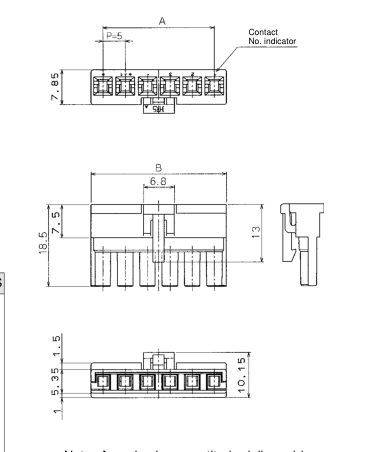
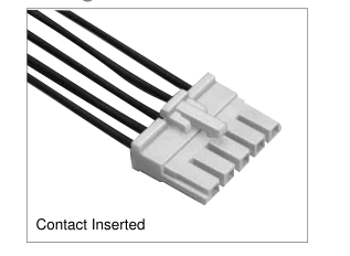
| Product No | CL No. | Number of Contacts | A | B | RoHS |
| DF5A- 2S-5C | 676-0007-8 | 2 | 5.0 | 10.5 | YES |
| DF5A- 3S-5C | 676-0008-0 | 3 | 10.0 | 15.5 | |
| DF5A- 4S-5C | 676-0009-3 | 4 | 15.0 | 20.5 | |
| DF5A- 5S-5C | 676-0010-2 | 5 | 20.0 | 25.5 | |
| DF5A- 6S-5C | 676-0011-5 | 6 | 25.0 | 30.5 | |
| DF5A- 7S-5C | 676-0012-8 | 7 | 30.0 | 35.5 | |
| DF5A- 8S-5C | 676-0013-0 | 8 | 35.0 | 40.5 | |
| DF5A- 9S-5C | 676-0014-3 | 9 | 40.0 | 45.5 | |
| DF5A-10S-5C | 676-0015-6 | 10 | 45.0 | 50.5 |
Note: A packaging quantity is delivered by the bag unit (100 pcs.).
■Single Row Pin Header
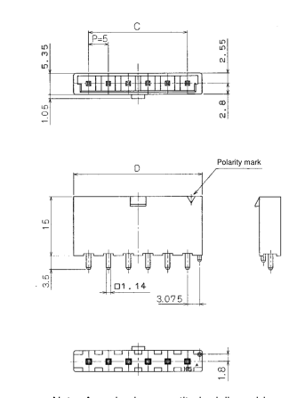
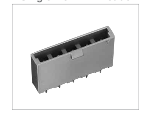
| Part Number | CL No. | Number of Contacts | C | D | RoHS |
|---|---|---|---|---|---|
| DF5A- 2P-5DSA(05) | 676-0016-9-05 | 2 | 5.0 | 12.5 | YES |
| DF5A- 3P-5DSA(05) | 676-0017-1-05 | 3 | 10.0 | 17.5 | |
| DF5A- 4P-5DSA(05) | 676-0018-4-05 | 4 | 15.0 | 22.5 | |
| DF5A- 5P-5DSA(05) | 676-0019-7-05 | 5 | 20.0 | 27.5 | |
| DF5A- 6P-5DSA(05) | 676-0020-6-05 | 6 | 25.0 | 32.5 | |
| DF5A- 7P-5DSA(05) | 676-0021-9-05 | 7 | 30.0 | 37.5 | |
| DF5A- 8P-5DSA(05) | 676-0022-1-05 | 8 | 35.0 | 42.5 | |
| DF5A- 9P-5DSA(05) | 676-0023-4-05 | 9 | 40.0 | 47.5 | |
| DF5A-10P-5DSA(05) | 676-0024-7-05 | 10 | 45.0 | 52.5 |
Note: A packaging quantity is delivered by the bag unit (100 pcs.).
B125
Page 4
All non-RoHS products have been discontinued, or will be discontinued soon. Please check the products status on the Hirose website RoHS search at www.hirose-connectors.com, or contact your Hirose sales representative.
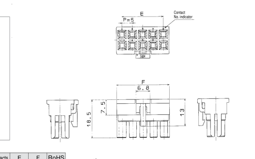
■Double Row Socket
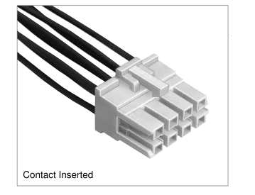
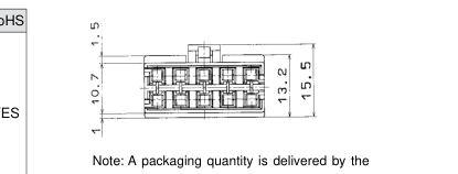
| Part Number | CL No. | Number of Contacts | E | F | RoHS |
|---|---|---|---|---|---|
| DF5A- 4DS-5C | 676-0025-0 | 4 | 5.0 | 10.5 | YES |
| DF5A- 6DS-5C | 676-0026-2 | 6 | 10.0 | 15.5 | |
| DF5A- 8DS-5C | 676-0027-5 | 8 | 15.0 | 20.5 | |
| DF5A-10DS-5C | 676-0028-8 | 10 | 20.0 | 25.5 | |
| DF5A-12DS-5C | 676-0036-6 | 12 | 25.0 | 30.5 | |
| DF5A-14DS-5C | 676-0037-9 | 14 | 30.0 | 35.5 | |
| DF5A-16DS-5C | 676-0038-1 | 16 | 35.0 | 40.5 |
bag unit (100 pcs.).
■Double Row Pin Header
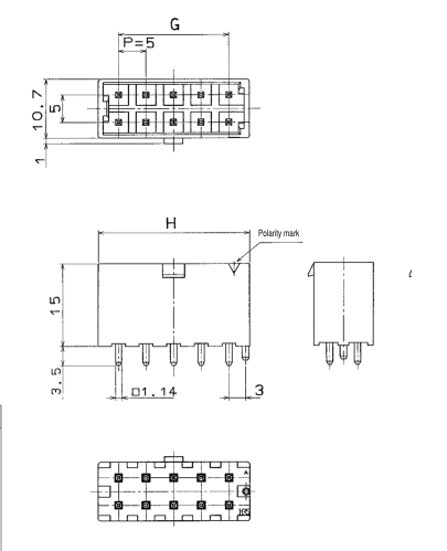
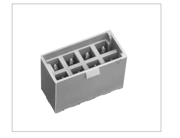
| Part Number | CL No. | Number of Contacts | G | H | RoHS |
|---|---|---|---|---|---|
| DF5A- 4DP-5DSA(05) | 676-0029-0-05 | 4 | 5.0 | 12.5 | YES |
| DF5A- 6DP-5DSA(05) | 676-0030-0-05 | 6 | 10.0 | 17.5 | |
| DF5A- 8DP-5DSA(05) | 676-0031-2-05 | 8 | 15.0 | 22.5 | |
| DF5A-10DP-5DSA(05) | 676-0032-5-05 | 10 | 20.0 | 27.5 | |
| DF5A-12DP-5DSA(05) | 676-0033-8-05 | 12 | 25.0 | 32.5 | |
| DF5A-14DP-5DSA(05) | 676-0034-0-05 | 14 | 30.0 | 37.5 | |
| DF5A-16DP-5DSA(05) | 676-0035-3-05 | 16 | 35.0 | 42.5 |
Note: A packaging quantity is delivered by the bag unit (100 pcs.).
B126
Page 5
All non-RoHS products have been discontinued, or will be discontinued soon. Please check the products status on the Hirose website RoHS search at www.hirose-connectors.com, or contact your Hirose sales representative.
BPCB mounting pattern (Board thickness = 1.6±0.1)
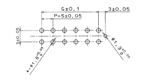
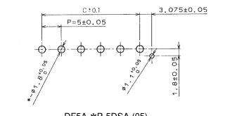
DF5A-\*P-5DSA (05)
DF5A-\*DP-5DSA (05)
Note 1. For C and G sizes, please refer to pages where individual product patterns are shown.
BApplication Pattern
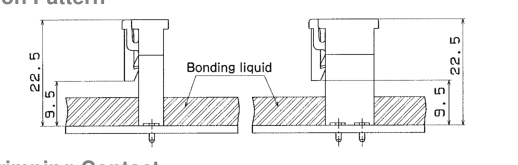
■Socket Crimping Contact
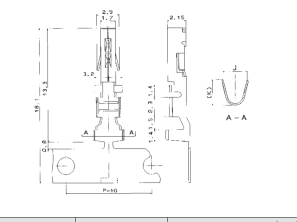
| Part Number | HRS. No. | Applicable Cable | Packaging Type | Quantity | J | K | RoHS | |||
|---|---|---|---|---|---|---|---|---|---|---|
| UL style | Jacket dia. | AWG size | Contact construction | |||||||
| DF5-1822SCF | 676-0001-1 | 1007 | 1.5 to 2.2 | AWG#18 AWG#20 AWG#22 | 43 cores/0.16mm 21 cores/0.18mm 17 cores/0.16mm | Reel | 5,000 | 2.8 | 3 | YES |
| DF5-1822SC | 676-0002-4 | Bag | 100 | |||||||
| DF5A-1822SCF | 676-0003-7 | 1015 | 2.2 to 3.2 | Reel | 5,000 | 3.8 | 4 | |||
| DF5A-1822SC | 676-0004-0 | Bag | 100 | |||||||
Note 1. The applicable cable conductor is a tin plated and annealed copper wire. Note 2. If other cables are used instead of the applicable cable, contact the HRS Sales Department. Strip length: 3 to 4mm
BApplicable Crimping Tools
| Type | Item | Part Number | CL No. | Applicable Contact |
|---|---|---|---|---|
| Auto- matic | Press unit | CM-105 | 901-0005-4 | ------------------------------ |
| Applicator | AP105-DF5-1822S | 901-4542-5 | DF5-1822SCF | |
| AP105-DF5A-1822S | 901-4546-6 | DF5A-1822SCF | ||
| Manual | Manual crimping tool | DF5-1822/CR-HT | 550-0264-0 | DF5-1822SC |
| DF5A-1822/CR-HT | 550-0265-2 | DF5A-1822SC | ||
| ----- | Extraction tool | RP13-PC-TP | 150-0021-5 | DF5/DF5A-1822SCF |
Note: If any trouble has been caused due to other tools, which are not designated by Hirose, Hirose won't guarantees any product.
B127
Page 6
All non-RoHS products have been discontinued, or will be discontinued soon. Please check the products status on the Hirose website RoHS search at www.hirose-connectors.com, or contact your Hirose sales representative.
BPrecautions
| 1. Recommended soldering condition | Flow: 260ç for 10 seconds Manual soldering: 350ç for 3 seconds |
|---|---|
| 2. Cleaning condition | Refer to the "Nylon Connector Use Hand book" |
| 3. Connecting condition | Refer to the "Nylon Connector Use Hand book" |
| 4. Cautions | ■The color phase of this product may be slightly differ from that of the formed product according to the manufacturing lot, and consequent storage condition, however, the difference affects no performance. |
| 5. Precautions | Refer to the "Nylon Connector Use Hand book" |
B128