

 Download PDF
DF3-2S-2R26 HIROSE
Document overview
- PDF pages: 12
Technical content
Page 1

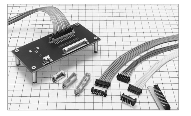
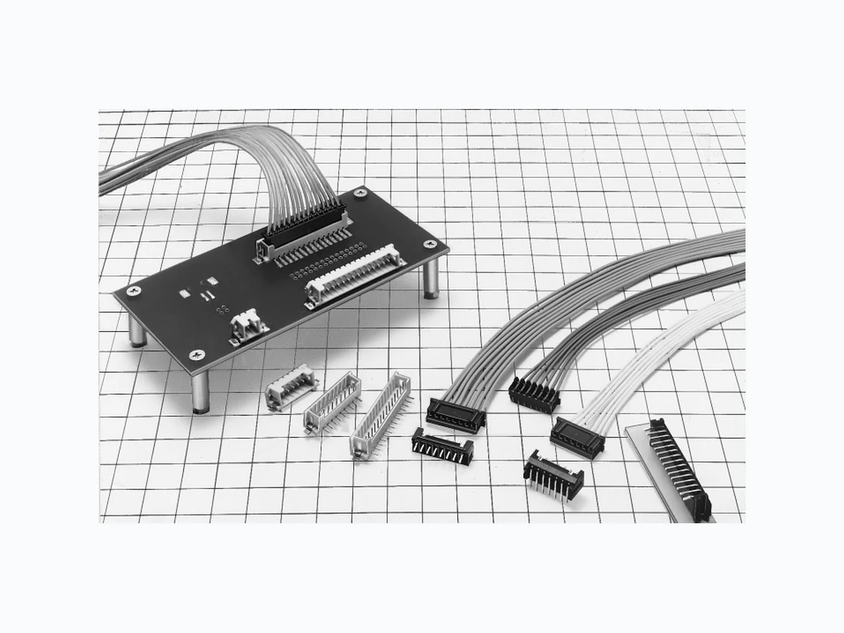
IFeatures
Correspond to Board Design in Wide Variation
(1) Low profile design with the mounting height of 6.8mm
GID Socket
(2) Achieves the multi-harness by the full automatic ID machine in combination with the DF11 series ID type. (DF11 series represents the 2mm pitch single-row product.Please refer to page A266 to A277.) (1) Low profile design with mounting height 7.5mm.
GCrimp Socket
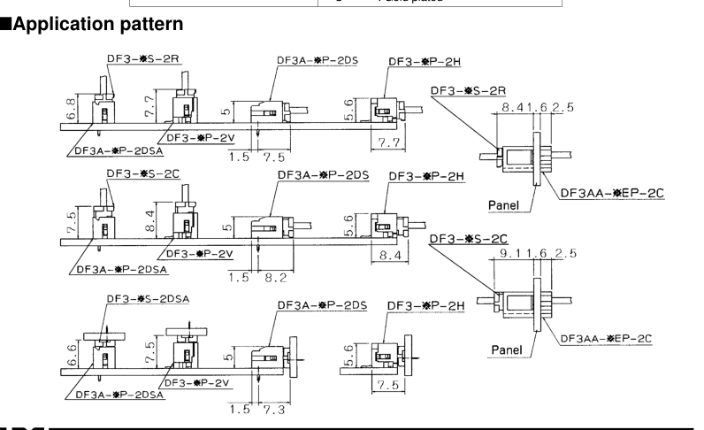
(Please refer to the application pattern figure on page A256 for details.) (2) Provide the contact crimping area with the sufficient space, and secures the stable crimping operation. (1) The board can be connected horizontally or vertically in combination with the straight header with the
GReceptacle
right angle header. (2) For horizontal connection, the board to board size is the low profile of 6.6mm. (Please refer to the application pattern on page A256 for details.) (3) Compatibility with the in-line plug allows the receptacle to set the board side to the receptacle and the cable side to the plug in the board to cable connection. (1) The board pre-fixed kink is treated with the post pin.
GPin Header
(2) The style employs a scoop-proof and sturborn box type. (3) The type corresponding to SMT is avilable, using the heat-proof resin. This SMT header is equipped with the metal tab to prevent peeling in the solder joint area. (1) The crimping in-line plug consits of two types, one type, which has pursued after space merits, and
GIn-line Plug
the other employs the panel lock type, which can be fixed to the panel. (2) The in-line adapter is available to insert and in-line the ID socket from both sides.
IApplications
Business equipment such as copy machine and printer
A254
Page 2
BEmbossed Carrier Tape Dimensions
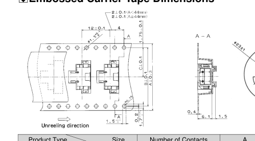
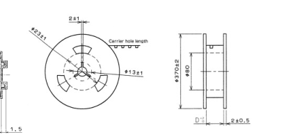
Unit: mm
| Product Type Size | Number of Contacts | A | B | C | D | |
|---|---|---|---|---|---|---|
| DF3/3D-*P-2H | 2 to 4 | 24 | ––– | 11.5 | 24.4 | |
| 5 to 7 | 32 | 28.4 | 14.2 | 32.4 | ||
| 8 to 12 | 44 | 40.4 | 20.2 | 44.4 | ||
| 13 to 15 | 56 | 52.4 | 26.2 | 56.4 | ||
| BPrecautions | ||||||
| 1. Recommended Temperature Profile (SMT) | Note1: Maximum twice action is allowed under the same condition. However, the interval between the first and second actions must be maintained at room temperature. Note2: The temperature indicates the board surface temperature on the connector lead area. | |||||
| 2. Recommended Manual Soldering Condition (SMT) | Soldering iron temperature: 290±10ç, Soldering time: Within 2 seconds | |||||
| 3. Recommended Screen Thickness (SMT) | 0.15 to 0.2mm | |||||
| 4. Board Warpage (SMT) | Based on both connector edges, 0.03mm max. in the connector center portion | |||||
| 5. Recommended Soldering Condition (DIP) | IFlow Condition with Automatic Soldering Tool. Soldering temperature: 250±5ç, Soldering time: Within 3 seconds IManual Soldering Condition. Soldering iron temperature: 290±10ç, Soldering time: Within 2 seconds | |||||
| 6. Cleaning Condition | Refer to the "Nylon Connector Use Hand book". | |||||
| 7. Connection Condition | Refer to the "Nylon Connector Use Hand book". | |||||
A265
Page 3
IProduct Specifications
| Rating | Current rating Note 1 | Crimping | AWG 22 to 24:3A Wire size AWG 26 :2A AWG 28 :1A | Operating Temperature Range Operating Humidity Range | -30ç to +85ç Note 2. 40% to 80% | ||
| Storage Temperature Range Storagg Humidity Range | -10ç to +60ç Note 3. 40% to 70% | ||||||
| IDC | Wire size AWG 26, 28:1A | ||||||
| Voltage rating AC100V | Crimping | Press-fit: 250V AC | IDC | Press-connect: 100V AC | |||
IUL CSA Safety Standard File No.
| UL-CSA Safety Standard and Approved specification | ||
| Rating | Rated Current | Wire size AWG 24 to 28: 1A |
| Rated Voltage | 30V AC | |
UL
:E52653
CSA
:LR95109
IUL CSA Acquisition Objective Item 1DF3-\*S-2C 2DF3/3A-\*P-2DSA/DS 3DF3/DF3AA-\*EP-2C 4DF3-\*S-2R26/28 5DF3-\*P-2H
| Item | Specification | Condition | |
|---|---|---|---|
| 1. Insulation Resistance | 1000M ohms min. | 500V DC | |
| 2. Withstanding voltage | No flashover or insulation breakdown. | 650V AC/1 minute | |
| 3. Contact Resistance | 30m ohms max | 100mA | |
| 4. Single Insertor/Extraction Force | MIN0.3N (30gf), MAX4.4N(450gf) | Measure by the square steel pin with 0.5±0.002mm | |
| 5. Vibration | No electrical discontinuity of 1µs or more | Frequency: 10 to 55 Hz, single amplitude of 0.75 mm, 2 hours in each of the 3 directions. | |
| 6. Humidity (Steady state) | Contact resistance: 30m ohms max.Insulation resistance: 500M ohms min. | 96 hours at temperature of 40ç and humidity of 90% to 95% | |
| 7. Temperature Cycle | Contact resistance: 30m ohms max.:Insulation resistance: 1000M ohms min. | (-55ç: 30 minutes 5 to 35ç: 10 minutes 85ç: 30 minutes 5 to 35ç: 10minutes) 5 cycles | |
| 8. Durability (Mating/un-mating) | Contact resistance: 30m ohms max. | Tin plating: 30 cycles Gold plating: 50 cycles | |
| 9. Resistance to Soldering Heat | No deformation of components affecting performance. | Flow: 250ç for 10 seconds | Manual soldering: 300ç for 2 seconds |
| Reflow: At the recommended temperature profile | Manual soldering: 300ç for 3 seconds | ||
Note 1: Includes temperature rise caused by current flow. Note 2: The term "storage" refers to products stored for long period of time prior to mounting and use. Operating Temperature Range and Humidity range covers non conducting condition of installed connectors in storage, shipment or during transportation.
IMaterial
| Product | Part | Materia | Finish | Remarks |
|---|---|---|---|---|
| Crimping Socket | Insulator | Polyamide | Black | UL94V-0 |
| IDC Contact for Socket | Contact | Phosphor bronze | Tin plated or gold plated | ––––––– |
| ID Socket | Insulator | Polyamide | Black | UL94V-0 |
| Contact | Phosphor bronze | Tin plated or gold plated | ––––––– | |
| Receptacle | Insulator | Polyamide | Black | UL94V-0 |
| Contact | Phosphor bronze | Tin plated or gold plated | ––––––– | |
| Pin Header | Insulator | Polyamide | Black | UL94V-0 |
| Contact | Brass | Tin plated or gold plated | ––––––– | |
| SMT Pin Header | Insulator | Polyamide | Beige | UL94V-0 |
| Contact | Phosphor bronze | Tin plated or gold plated | ––––––– | |
| Metal tab | Brass | Tin plated | ––––––– | |
| In-line Plug | Insulator | Polyamide | Black | UL94V-0 |
| In-line IDC Contact | Contact | Phosphor bronze | Tin plated or gold plated | ––––––– |
| In-line Adapter | Insulator | Polyamide | Black | UL94V-0 |
| Contact | Brass | Tin plated | ––––––– |
Note:HRS's tin plating takes actions against whisker.
A255
Page 4
IOrdering Information
GConnector
DF 3 - \* S - 2C
q w
e r
t y
| q Series Name : DF | y Connection Form/Contact Style C : Crimp socket R26 : ID socket for AWG26 R28 : ID socket for AWG28 DSA : Straight through hole DS : Right angle through hole V : Straight SMT H : Right angle SMT A : Adapter |
| w Series No. : 3, 3A, 3AA | |
| e Number of Contacts : 2~15 | |
| r Connector Type S : Socket P : Pin Header EP : In-line Plug | |
| t Contact Pitch : 2mm |
GContact
DF3 - EP2428PCFA
q w e r
| q Contact Type NONE : For socket EP : For in-line plug | e Contact Type/Packaging Type SCF : Socket contact, Embossed tape SC : Socket contact, Bag PCF : Plug contact, Embossed tape PC : Plug contact, Bag |
| w Applicable Wire Size 22 : AWG22 2428 : AWG24 to 28 | |
| r Plating Type Blank : Tin plated A : Gold plated C : Gold plated |
A256
Page 5
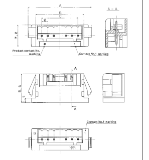
IID Socket
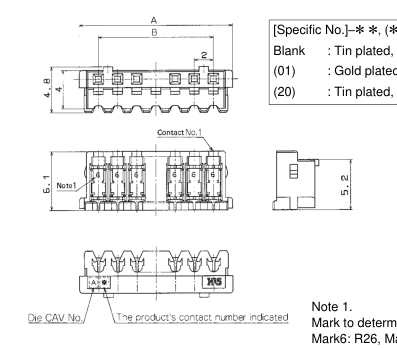
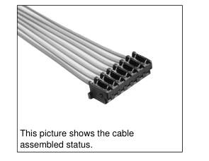
Mark to determine the socket name Mark6: R26, Mark8: R28
GAWG28
GAWG26
Unit: mm Unit: mm
Unit: mm
| Part Number | CL No. | Number of Contacts | A | B | Tube packaging Quantity |
|---|---|---|---|---|---|
| DF3- 2S-2R26(**) | 543-0078-7-** | 2 | 6 | 2 | 190 pieces |
| DF3- 3S-2R26(**) | 543-0079-0-** | 3 | 8 | 4 | 142 |
| DF3- 4S-2R26(**) | 543-0080-9-** | 4 | 10 | 6 | 114 |
| DF3- 5S-2R26(**) | 543-0081-1-** | 5 | 12 | 8 | 094 |
| DF3- 6S-2R26(**) | 543-0082-4-** | 6 | 14 | 10 | 080 |
| DF3- 7S-2R26(**) | 543-0083-7-** | 7 | 16 | 12 | 070 |
| DF3- 8S-2R26(**) | 543-0084-0-** | 8 | 18 | 14 | 062 |
| DF3- 9S-2R26(**) | 543-0085-2-** | 9 | 20 | 16 | 056 |
| DF3-10S-2R26(**) | 543-0086-5-** | 10 | 22 | 18 | 052 |
| DF3-11S-2R26(**) | 543-0087-8-** | 11 | 24 | 20 | 046 |
| DF3-12S-2R26(**) | 543-0088-0-** | 12 | 26 | 22 | 044 |
| DF3-13S-2R26(**) | 543-0089-3-** | 13 | 28 | 24 | 040 |
| DF3-14S-2R26(**) | 543-0090-2-** | 14 | 30 | 26 | 038 |
| DF3-15S-2R26(**) | 543-0091-5-** | 15 | 32 | 28 | 034 |
| Part Number | CL No. | Number of Contacts | A | B | Tube packaging Quantity |
|---|---|---|---|---|---|
| DF3- 2S-2R28(**) | 543-0092-8-** | 2 | 6 | 2 | 190 pieces |
| DF3- 3S-2R28(**) | 543-0093-0-** | 3 | 8 | 4 | 142 |
| DF3- 4S-2R28(**) | 543-0094-3-** | 4 | 10 | 6 | 114 |
| DF3- 5S-2R28(**) | 543-0095-6-** | 5 | 12 | 8 | 094 |
| DF3- 6S-2R28(**) | 543-0096-9-** | 6 | 14 | 10 | 080 |
| DF3- 7S-2R28(**) | 543-0097-1-** | 7 | 16 | 12 | 070 |
| DF3- 8S-2R28(**) | 543-0098-4-** | 8 | 18 | 14 | 062 |
| DF3- 9S-2R28(**) | 543-0099-7-** | 9 | 20 | 16 | 056 |
| DF3-10S-2R28(**) | 543-0100-4-** | 10 | 22 | 18 | 052 |
| DF3-11S-2R28(**) | 543-0101-7-** | 11 | 24 | 20 | 046 |
| DF3-12S-2R28(**) | 543-0102-0-** | 12 | 26 | 22 | 044 |
| DF3-13S-2R28(**) | 543-0103-2-** | 13 | 28 | 24 | 040 |
| DF3-14S-2R28(**) | 543-0104-5-** | 14 | 30 | 26 | 038 |
| DF3-15S-2R28(**) | 543-0105-8-** | 15 | 32 | 28 | 034 |
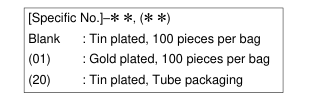
Note 2.The quantity for delivery of the specific No. "None" and (01) is determined per bag (100pcs.). If needed, please order the productsper bag. Note 3.If the Full automatic IDC machine to hit the DF11 single core,the (20) tube packaging specification will be applied. Note 4.Order the tube packaging product, multiplying the tube packaging quantity (pieces).
IApplicable Cable
| Part Number | Applicable Cable | Jacket Diameter |
|---|---|---|
| DF3-*S-2R26 | UL1061 AWG26 (7/0.16) | Ø0.9 to 1mm |
| DF3-*S-2R28 | UL1061 AWG28 (7/0.127) | Ø0.9 to 1mm |
IApplicable ID Connection Tool
| Type | Part Number | Connection Type | Remarks |
|---|---|---|---|
| DF11 Single Contact Punching Full Automatic ID Machine | AM700/DF11 | I Effective Harness Form 1DF11-Both ended, single ended 2DF11-DF11, Separation 3DF11-DF3, Separation I Effective Harness Length 100 to 2,000mm I Conduction Inspection Mechanism Installed | Connector is the specification (20). Tube packaging applied |
| DF3 DF4 Desktop ID Machine | DF3(4)/ID-MO | DF3 No restriction DF4 No restriction | Desktop machine for small lot |
A257
Page 6
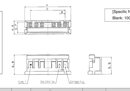
ICrimping Socket
[Specific No.] –\* \*, (\* \*)
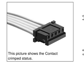
Blank: 100 pieces per pack
Unit: mm
| Part Number | CL No. | Number of Contacts | A | B | Part Number | CL No. | Number of Contacts | A | B |
|---|---|---|---|---|---|---|---|---|---|
| DF3-2S-2C(**) | 543-0003-8-** | 2 | 06 | 02 | DF3-19S-2C(**) | 543-0010-3-** | 09 | 20 | 16 |
| DF3-3S-2C(**) | 543-0004-0-** | 3 | 08 | 04 | DF3-10S-2C(**) | 543-0011-6-** | 10 | 22 | 18 |
| DF3-4S-2C(**) | 543-0005-3-** | 4 | 10 | 06 | DF3-11S-2C(**) | 543-0012-9-** | 11 | 24 | 20 |
| DF3-5S-2C(**) | 543-0006-6-** | 5 | 12 | 08 | DF3-12S-2C(**) | 543-0013-1-** | 12 | 26 | 22 |
| DF3-6S-2C(**) | 543-0007-9-** | 6 | 14 | 10 | DF3-13S-2C(**) | 543-0014-4-** | 13 | 28 | 24 |
| DF3-7S-2C(**) | 543-0008-1-** | 7 | 16 | 12 | DF3-14S-2C(**) | 543-0015-7-** | 14 | 30 | 26 |
| DF3-8S-2C(**) | 543-0009-4-** | 8 | 18 | 14 | DF3-15S-2C(**) | 543-0016-0-** | 15 | 32 | 28 |
Note1: The product's contact number indicated. Note2: The quantity for delivery of the specification No. "None" is determined per bag (100 pcs.). If needed, please order the products per bag. Note3: A quantity of "500 pieces package" and "1000 pieces package" for delivery is dealt with pieces. Order example: 500, 1000, and 1500 pieces...
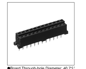
IReceptacle
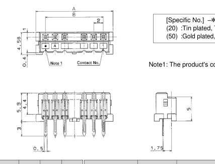
[Specific No.] –\* \*, (\* \*) (20) :Tin plated, Tube packaging (50) :Gold plated, Tube packaging
Note1: The product's contact number indicated
GBoard Through-hole Diameter: Ø0.7+0
Unit: mm
| Part Number | CL No. | Number of Contacts | A | B | Tube Package Quantity | Part Number | CL No. | Number of Contacts | A | B | Tube Package Quantity |
|---|---|---|---|---|---|---|---|---|---|---|---|
| DF3-2S-2DSA(**) | 543-0048-6-** | 2 | 06 | 02 | 80 pieces | DF3- 9S-2DSA(**) | 543-0055-1-** | 09 | 20 | 16 | 24 pieces |
| DF3-3S-2DSA(**) | 543-0049-9-** | 3 | 08 | 04 | 60 | DF3-10S-2DSA(**) | 543-0056-4-** | 10 | 22 | 18 | 21 |
| DF3-4S-2DSA(**) | 543-0050-8-** | 4 | 10 | 06 | 48 | DF3-11S-2DSA(**) | 543-0057-7-** | 11 | 24 | 20 | 20 |
| DF3-5S-2DSA(**) | 543-0051-0-** | 5 | 12 | 08 | 40 | DF3-12S-2DSA(**) | 543-0058-0-** | 12 | 26 | 22 | 18 |
| DF3-6S-2DSA(**) | 543-0052-3-** | 6 | 14 | 10 | 34 | DF3-13S-2DSA(**) | 543-0059-2-** | 13 | 28 | 24 | 17 |
| DF3-7S-2DSA(**) | 543-0053-6-** | 7 | 16 | 12 | 30 | DF3-14S-2DSA(**) | 543-0060-1-** | 14 | 30 | 26 | 16 |
| DF3-8S-2DSA(**) | 543-0054-9-** | 8 | 18 | 14 | 27 | DF3-15S-2DSA(**) | 543-0061-4-** | 15 | 32 | 28 | 15 |
Note2: Please order the tube packaging at the multiplied tube packaging quantity (pieces).
A258
Page 7
IStraight Pin Header
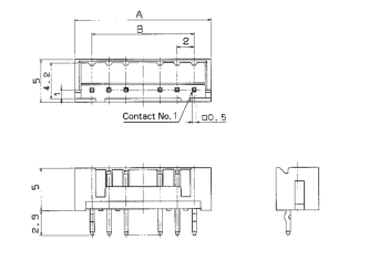
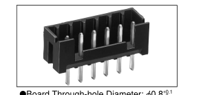
GBoard Through-hole Diameter: Ø0.8+0
+0.05
GKink Pre-fixed Effective Diameter: Ø0.8+0
Unit: mm
| Tin Plating | Gold Plating | Number of Contacts | A | B | ||
| Part Number | CL No. | Part Number | CL No. | |||
| DF3A- 2P-2DSA | 543-0165-0 | DF3- 2P-2DSA(01) | 543-0017-2-01 | 2 | 06 | 02 |
| DF3A- 3P-2DSA | 543-0166-2 | DF3- 3P-2DSA(01) | 543-0018-5-01 | 3 | 08 | 04 |
| DF3A- 4P-2DSA | 543-0167-5 | DF3- 4P-2DSA(01) | 543-0019-8-01 | 4 | 10 | 06 |
| DF3A- 5P-2DSA | 543-0168-8 | DF3- 5P-2DSA(01) | 543-0020-7-01 | 5 | 12 | 08 |
| DF3A- 6P-2DSA | 543-0169-0 | DF3- 6P-2DSA(01) | 543-0021-0-01 | 6 | 14 | 10 |
| DF3A- 7P-2DSA | 543-0170-0 | DF3- 7P-2DSA(01) | 543-0022-2-01 | 7 | 16 | 12 |
| DF3A- 8P-2DSA | 543-0171-2 | DF3- 8P-2DSA(01) | 543-0023-5-01 | 8 | 18 | 14 |
| DF3A- 9P-2DSA | 543-0172-5 | DF3- 9P-2DSA(01) | 543-0024-8-01 | 9 | 20 | 16 |
| DF3A-10P-2DSA | 543-0173-8 | DF3-10P-2DSA(01) | 543-0025-0-01 | 10 | 22 | 18 |
| DF3A-11P-2DSA | 543-0174-0 | DF3-11P-2DSA(01) | 543-0026-3-01 | 11 | 24 | 20 |
| DF3A-12P-2DSA | 543-0175-3 | DF3-12P-2DSA(01) | 543-0027-6-01 | 12 | 26 | 22 |
| DF3A-13P-2DSA | 543-0176-6 | DF3-13P-2DSA(01) | 543-0028-9-01 | 13 | 28 | 24 |
| DF3A-14P-2DSA | 543-0177-9 | DF3-14P-2DSA(01) | 543-0029-1-01 | 14 | 30 | 26 |
| DF3A-15P-2DSA | 543-0178-1 | DF3-15P-2DSA(01) | 543-0030-0-01 | 15 | 32 | 28 |
| Note : The quantity for delivery is determined per bag (100 pcs.). If needed, please order the products per bag. IRight Angle Pin Header GBoard Through-hole Diameter: Ø0.8+0.1 +0 GKink Pre-fixed Effective Diameter: Ø0.8+0.05 +0 Unit: mm | ||||||
| Tin Plating | Gold Plating | Number of Contacts | A | B | ||
| Part Number | CL No. | Part Number | CL No. | |||
| DF3A- 2P-2DS | 543-0179-4 | DF3- 2P-2DS(01) | 543-0031-3-01 | 2 | 06 | 02 |
| DF3A- 3P-2DS | 543-0180-3 | DF3 -3P-2DS(01) | 543-0032-6-01 | 3 | 08 | 04 |
| DF3A- 4P-2DS | 543-0181-6 | DF3- 4P-2DS(01) | 543-0033-9-01 | 4 | 10 | 06 |
| DF3A- 5P-2DS | 543-0182-9 | DF3- 5P-2DS(01) | 543-0034-1-01 | 5 | 12 | 08 |
| DF3A- 6P-2DS | 543-0183-1 | DF3- 6P-2DS(01) | 543-0035-4-01 | 6 | 14 | 10 |
| DF3A- 7P-2DS | 543-0184-4 | DF3- 7P-2DS(01) | 543-0036-7-01 | 7 | 16 | 12 |
| DF3A- 8P-2DS | 543-0185-7 | DF3- 8P-2DS(01) | 543-0037-0-01 | 8 | 18 | 14 |
| DF3A- 9P-2DS | 543-0186-0 | DF3- 9P-2DS(01) | 543-0038-2-01 | 9 | 20 | 16 |
| DF3A-10P-2DS | 543-0187-2 | DF3-10P-2DS(01) | 543-0039-5-01 | 10 | 22 | 18 |
| DF3A-11P-2DS | 543-0188-5 | DF3-11P-2DS(01) | 543-0040-4-01 | 11 | 24 | 20 |
| DF3A-12P-2DS | 543-0189-8 | DF3-12P-2DS(01) | 543-0041-7-01 | 12 | 26 | 22 |
| DF3A-13P-2DS | 543-0190-7 | DF3-13P-2DS(01) | 543-0042-0-01 | 13 | 28 | 24 |
| DF3A-14P-2DS | 543-0191-0 | DF3-14P-2DS(01) | 543-0043-2-01 | 14 | 30 | 26 |
| DF3A-15P-2DS | 543-0192-2 | DF3-15P-2DS(01) | 543-0044-5-01 | 15 | 32 | 28 |
Note : The quantity for delivery is determined per bag(100 pcs.). If needed, please order the products per bag.
A259
Page 8
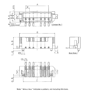
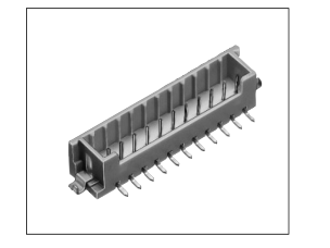
IStraight Pin Header (SMT)
BPCB mounting pattern
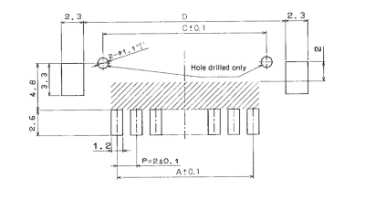
Note : If a pattern is included in the shaded area and is not treated with resist,
[Specific No.] –\* \*, (\* \*)
it could touch the connector contact.
(20) :Tin plated tube packaging (50) :Gold plated tube packaging
Unit: mm
| With Boss | Without Boss | Number of Contacts | A | B | C | D | Tube Packaging Quantity | ||
| Part Number | CL No. | Part Number | CL No. | ||||||
| DF3- 2P-2V(**) | 543-0121-4-** | DF3D- 2P-2V(**) | 543-0207-8-** | 2 | 02 | 8.5 | 4.8 | 8.74 | 41 pcs. |
| DF3- 3P-2V(**) | 543-0122-7-** | DF3D- 3P-2V(**) | 543-0208-0-** | 3 | 04 | 10.5 | 6.8 | 10.74 | 34 |
| DF3- 4P-2V(**) | 543-0123-0-** | DF3D- 4P-2V(**) | 543-0209-3-** | 4 | 06 | 12.5 | 8.8 | 12.74 | 30 |
| DF3- 5P-2V(**) | 543-0124-2-** | DF3D- 5P-2V(**) | 543-0210-2-** | 5 | 08 | 14.5 | 10.8 | 14.74 | 26 |
| DF3- 6P-2V(**) | 543-0125-5-** | DF3D- 6P-2V(**) | 543-0211-5-** | 6 | 10 | 16.5 | 12.8 | 16.74 | 23 |
| DF3- 7P-2V(**) | 543-0126-8-** | DF3D- 7P-2V(**) | 543-0212-8-** | 7 | 12 | 18.5 | 14.8 | 18.74 | 21 |
| DF3- 8P-2V(**) | 543-0127-0-** | DF3D- 8P-2V(**) | 543-0213-0-** | 8 | 14 | 20.5 | 16.8 | 20.74 | 19 |
| DF3- 9P-2V(**) | 543-0128-3-** | DF3D- 9P-2V(**) | 543-0214-3-** | 9 | 16 | 22.5 | 18.8 | 22.74 | 18 |
| DF3-10P-2V(**) | 543-0129-6-** | DF3D-10P-2V(**) | 543-0215-6-** | 10 | 18 | 24.5 | 20.8 | 24.74 | 17 |
| DF3-11P-2V(**) | 543-0130-5-** | DF3D-11P-2V(**) | 543-0216-9-** | 11 | 20 | 26.5 | 22.8 | 26.74 | 15 |
| DF3-12P-2V(**) | 543-0131-8-** | DF3D-12P-2V(**) | 543-0217-1-** | 12 | 22 | 28.5 | 24.8 | 28.74 | 14 |
| DF3-13P-2V(**) | 543-0132-0-** | DF3D-13P-2V(**) | 543-0218-4-** | 13 | 24 | 30.5 | 26.8 | 30.74 | 14 |
| DF3-14P-2V(**) | 543-0133-3-** | DF3D-14P-2V(**) | 543-0219-7-** | 14 | 26 | 32.5 | 28.8 | 32.74 | 13 |
| DF3-15P-2V(**) | 543-0134-6-** | DF3D-15P-2V(**) | 543-0220-6-** | 15 | 28 | 34.5 | 30.8 | 34.74 | 12 |
Note : Please order the tube packaging product, multiplying by tube package quantity ( pcs.).
A260
Page 9
IRight Angle Pin Header (SMT)
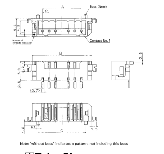
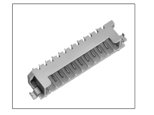
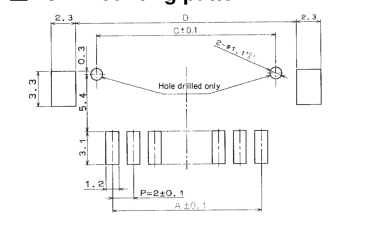
BPCB mounting pattern
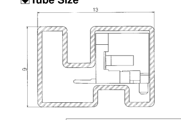
BTube Size
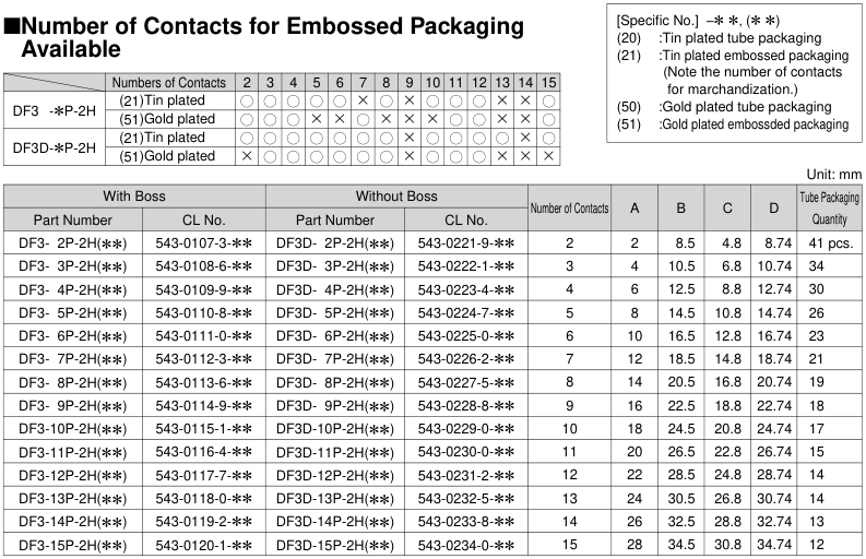
| Numbers of Contacts | 2 | 3 | 4 | 5 | 6 | 7 | 8 | 9 | 10 | 11 | 12 | 13 | 14 | 15 | |
| DF3D-*P-2H | (21)Tin plated | K | K | K | K | K | ∞ | K | ∞ | K | K | K | ∞ | ∞ | K |
| (51)Gold plated | K | K | K | ∞ | ∞ | K | ∞ | ∞ | ∞ | K | K | ∞ | ∞ | K | |
| DF3D-*P-2H | (21)Tin plated | K | K | K | K | K | K | K | ∞ | K | K | K | K | ∞ | K |
| (51)Gold plated | ∞ | K | K | K | K | K | K | ∞ | K | K | K | ∞ | ∞ | ∞ |
Note1: Please order the tube packaging product, multipliing the tube package quantity. ( pcs.) Note2: Please order the emboss packaging product by the reel number. (1 reel : 1000 pcs.)
A261
Page 10
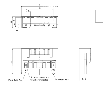
IIn-line Plug
[Specific No.] –\* \*, (\* \*)
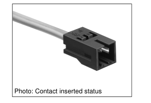
Blank: 1 pack
Unit: mm
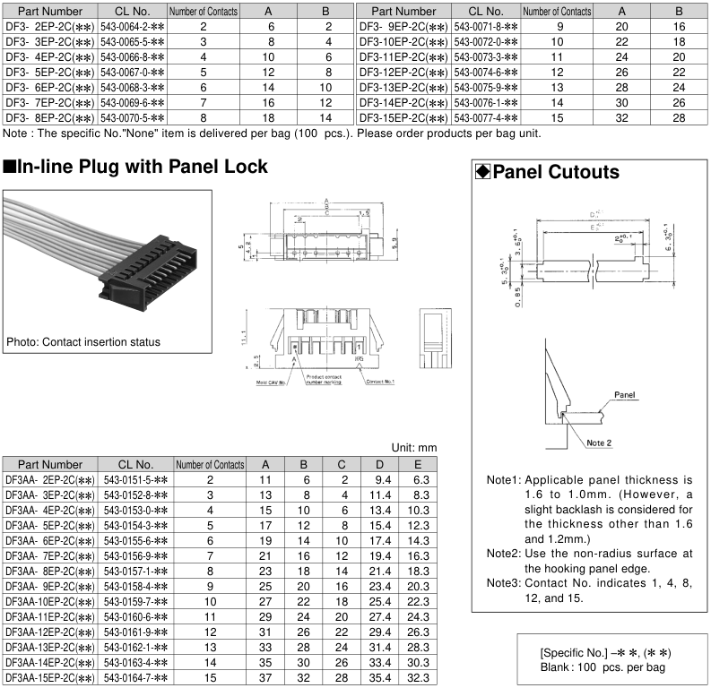
Note : Specific No."None" item is delivered per bag (100 pcs.). Please order products per bag unit.
A262
Page 11
IIn-line Adapter with Panel Lock
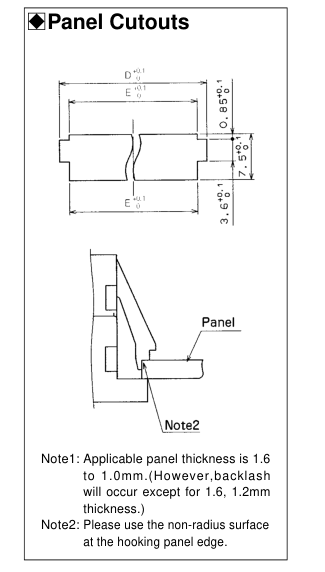
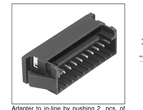
socket from both sides No.1-No.1 connection circuit type
Unit: mm
| Part Number | CL No. | Number of Contacts | A | B | C | D | E |
|---|---|---|---|---|---|---|---|
| DF3- 2EP-2A(**) | 543-0267-0-** | 2 | 11 | 06 | 02 | 9.4 | 6.3 |
| DF3- 3EP-2A(**) | 543-0268-2-** | 3 | 13 | 08 | 04 | 11.4 | 8.3 |
| DF3- 4EP-2A(**) | 543-0269-5-** | 4 | 15 | 10 | 06 | 13.4 | 10.3 |
| DF3- 5EP-2A(**) | 543-0270-4-** | 5 | 17 | 12 | 08 | 15.4 | 12.3 |
| DF3- 6EP-2A(**) | 543-0271-7-** | 6 | 19 | 14 | 10 | 17.4 | 14.3 |
| DF3- 7EP-2A(**) | 543-0272-0-** | 7 | 21 | 16 | 12 | 19.4 | 16.3 |
| DF3- 8EP-2A(**) | 543-0273-2-** | 8 | 23 | 18 | 14 | 21.4 | 18.3 |
| DF3- 9EP-2A(**) | 543-0274-5-** | 9 | 25 | 20 | 16 | 23.4 | 20.3 |
| DF3-10EP-2A(**) | 543-0275-8-** | 10 | 27 | 22 | 18 | 25.4 | 22.3 |
| DF3-11EP-2A(**) | 543-0276-0-** | 11 | 29 | 24 | 20 | 27.4 | 24.3 |
| DF3-12EP-2A(**) | 543-0277-3-** | 12 | 31 | 26 | 22 | 29.4 | 26.3 |
| DF3-13EP-2A(**) | 543-0278-6-** | 13 | 33 | 28 | 24 | 31.4 | 28.3 |
| DF3-14EP-2A(**) | 543-0279-9-** | 14 | 35 | 30 | 26 | 33.4 | 30.3 |
| DF3-15EP-2A(**) | 543-0280-8-** | 15 | 37 | 32 | 28 | 35.4 | 32.3 |
[Specific No.] –\* \*, (\* \*) Blank : 100 pcs. per bag
Note : Specific No."None" item is delivered per bag (100 pcs.). Please order products per bag unit.
A263
Page 12
ICrimping Contact for Socket
| Part Number | CL No. | Type | Quantity | Finish |
|---|---|---|---|---|
| DF3-22SCF | 543-0235-3 | Reel contact | 10000 pcs. per embossed tape bag | Tin plated |
| DF3-22SC | 543-0236-6 | Bulk contact | 100 pcs. per embossed tape bag | |
| DF3-2428SCF | 543-0001-2 | Reel contact | 10000 pcs. per embossed tape bag | |
| DF3-2428SC | 543-0002-5 | Bulk contact | 100 pcs. per embossed tape bag | |
| DF3-2428SCFC | 543-0046-0 | Reel contact | 10000 pcs. per embossed tape bag | Gold plated |
| DF3-248SCC | 543-0047-3 | Bulk contact | 100 pcs. per embossed tape bag | |
| GApplicable Wire (Tin Plating Annealed GRecommended Wire Copper Wire) UL1061, UL1007 (Note 2.) GStrip Length Conductor Size (Wire Configuration) Jacket Diameter AWG 22 (17pcs./0.16mm) Ø1.2 to Ø1.45mm 1.8 to 2.3mm AWG 24 (11pcs./0.16mm) AWG 26 (7pcs./0.16mm) Ø0.75 to Ø1.45mm AWG 28 (7pcs./0.127mm) Note1: If other wires are used instead of the applicable cable, please contact HRS company. Note2: DF3-22SCF is applicable to UL1061. | ||||
| -line Plug | ||||
| Part Number | CL No. | Type | Quantity | Finish |
| DF3-EP2428PCF | 543-0062-7 | Reel contact | 10000 pcs. per reel | Tin plated |
| DF3-EP2428PC | 543-0063-0 | Bulk contact | 100 pcs. per pack | |
| DF3-EP2428PCFA | 543-0149-3 | Reel contact | 10000 pcs. per reel | Gold plated |
| DF3-EP2428PCA | 543-0150-2 | Bulk contact | 100 pcs. per pack | |
| GApplicable Wire (Tin Plating Annealed GRecommended Wire Copper Wire) UL1061, UL1007 GStrip Length Conductor Size (Wire Configuration) Jacket Diameter AWG 24 (11pcs./0.16mm) 1.9 to 2.5mm AWG 26 (7pcs./0.16mm) Ø0.75 to Ø1.45mm AWG 28 (7pcs./0.127mm) Note1: If other wires are used instead of the applicable cable, please contact HRS company. | ||||
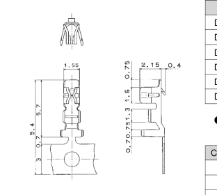
| Conductor Size (Wire Configuration) | Jacket Diameter |
| AWG 22 (17pcs./0.16mm) | Ø1.2 to Ø1.45mm |
| AWG 24 (11pcs./0.16mm) | Ø0.75 to Ø1.45mm |
| AWG 26 (7pcs./0.16mm) | |
| AWG 28 (7pcs./0.127mm) |
ICrimping Contact for In-line Plug
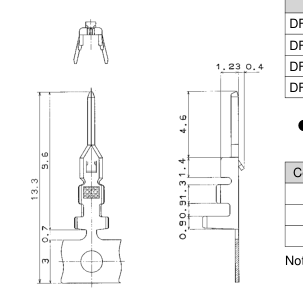
| Conductor Size (Wire Configuration) | Jacket Diameter |
| AWG 24 (11pcs./0.16mm) | Ø0.75 to Ø1.45mm |
| AWG 26 (7pcs./0.16mm) | |
| AWG 28 (7pcs./0.127mm) |
BApplicable Crimping Tool
| Type | Part Number | CL No. | Applicable Contact |
|---|---|---|---|
| Applicator | AP105-DF3-2428S | 901-4503-3 | DF3-2428SCF/SCFC |
| AP105-DF3-22S | 901-4549-4 | DF3-22SCF | |
| AP105-DF3-EP2428P | 901-4508-7 | DF3-EP2428PCF/PCFA | |
| Press Unit | CM-105 | 901-0005-4 | ––––––––––––––––––– |
| Hand Crimping Tool | DF3-TA2428HC | 550-0164-5 | DF3-2428SC/SCC |
| DF3EP-TA2428HC | 550-0184-2 | DF3-EP2428PC/PCA | |
| DF3-TA22HC | 550-0257-4 | DF3-22SC | |
| Extraction Tool | DF-C-PO (A) | 550-0170-8 | DF3-****SCF |
| DF3-EP****PCF |
Note : If any trouble has occurred due to tools other than designated tool, Hirose bears no respoisibility for any trouble.
A264