
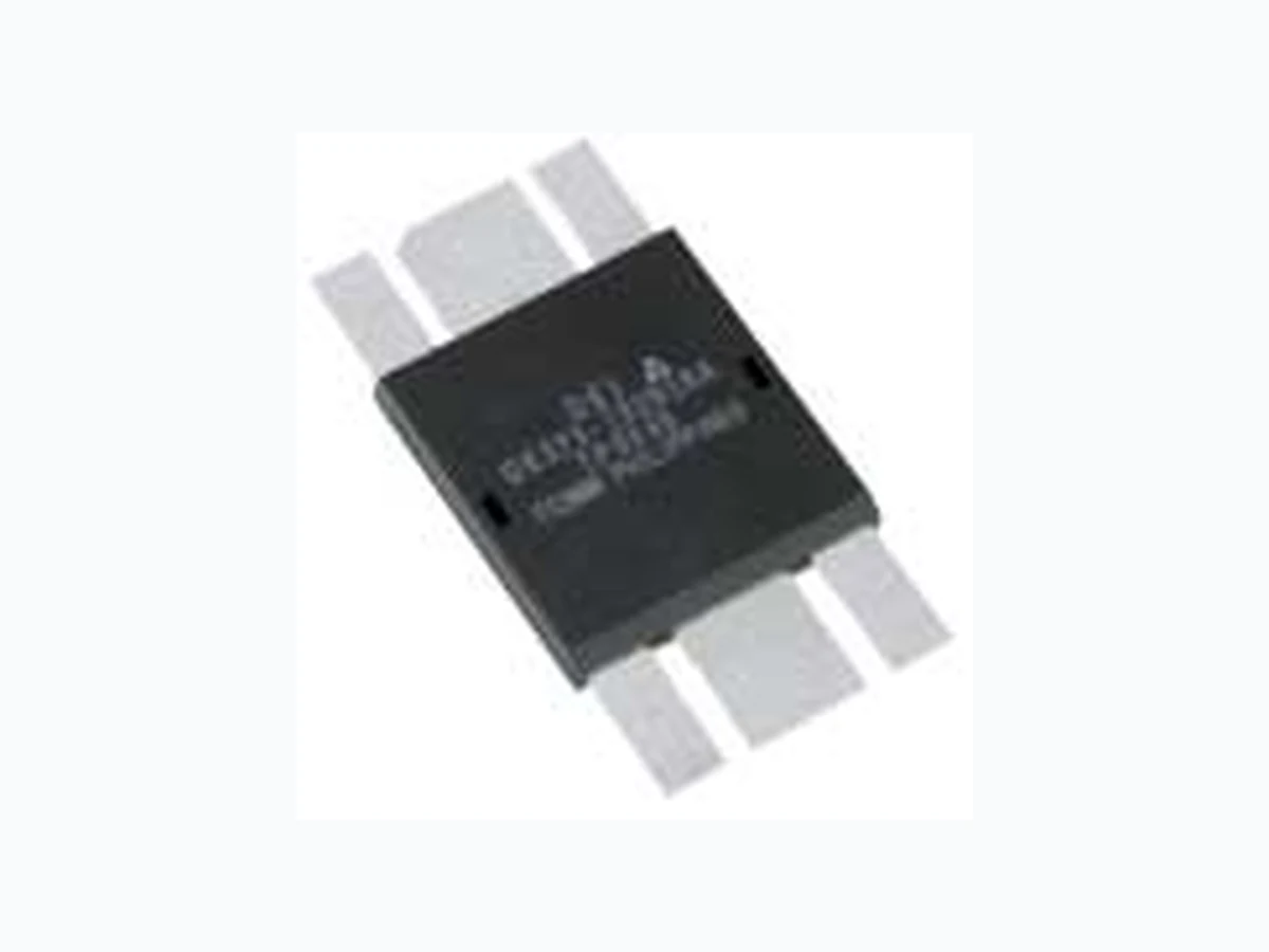
DE375-102N12A ETC1
Document overview
- Manufacturer or author: Provided By www.digicamel.com(FREE DATASHEET DOWNLOAD SITE)
- PDF pages: 3
Technical content
Features
- Isolated Substrate high isolation voltage (>2500V) excellent thermal transfer Increased temperature and power cycling capability
- IXYS advanced low Qg process
- Low gate charge and capacitances easier to drive faster switching
- Low RDS(on)
- Very low insertion inductance (<2nH)
- No beryllium oxide (BeO) or other haz- ardous materials Advantages
- Optimized for RF and high speed switching at frequencies to 50MHz
- Easy to mount—no insulators needed
- High power density N-Channel Enhancement Mode Low Qg and Rg High dv/dt Nanosecond Switching 50MHz Maximum Frequency DRAIN SG1 SG2 GATE SD1 SD2
Directed Energy, Inc. An IXYS Company Symbol Test Conditions Characteristic Values (TJ = 25°C unless otherwise specified) min. typ. max. RG 0.3 Ω Ciss 2700 pF Coss VGS = 0 V, VDS = 0.8 VDSS(max), f = 1 MHz 305 pF Crss pF Td(on) ns Ton VGS = 15 V, VDS = 0.8 VDSS ID = 0.5 IDM RG = 0.2 Ω (External) ns Td(off) ns Toff ns Qg(on) nC Qgs VGS = 10 V, VDS = 0.5 VDSS ID = 0.5 ID25 nC Qgd nC RthJHS 0.23 K/W Source-Drain Diode Characteristic Values (TJ = 25°C unless otherwise specified) Symbol Test Conditions min. typ. max. IS VGS = 0 V A ISM Repetitive; pulse width limited by TJM A VSD 1.5 V Trr 200 ns IF = IS, VGS = 0 V, Pulse test, t ≤ 300 µs, duty cycle ≤ 2% QRM IF = IS, -di/dt = 100A/µs, VR = 100V 0.6 µC IRM A Directed Energy, Inc. reserves the right to change limits, test conditions and dimensions. DEI MOSFETS are covered by one or more of the following U.S. patents: 4,835,592 4,850,072 4,881,106 4,891,686 4,931,844 5,017,508 5,034,796 5,049,961 5,063,307 5,187,117 5,237,481 5,486,715 5,381,025 5,640,045 For detailed device mounting and installation instructions, see the “DE- Series MOSFET Mounting Instructions” technical note on DEI’s web site at www.directedenergy.com/apptech.htm
Directed Energy, Inc. An IXYS Company Directed Energy, Inc. An IXYS Company 2401 Research Blvd., Suite 108 Fort Collins, CO USA 80526 970-493-1901 Fax: 970-493-1903 Email: deiinfo@directedenergy.com Web: http://www.directedenergy.com 102N12A DE-SERIES SPICE Model (Preliminary) The DE-SERIES SPICE Model is illustrated in Figure 1. The model is an expan- sion of the SPICE level 3 MOSFET model. It includes the stray inductive terms LG, LS and LD. Rd is the RDS(ON) of the device, Rds is the resistive leakage term. The output capacitance, COSS, and reverse transfer capacitance, CRSS are mod- eled with reversed biased diodes. This provides a varactor type response neces- sary for a high power device model. The turn on delay and the turn off delay are adjusted via Ron and Roff. Figure 1 DE-SERIES SPICE Model This SPICE model may be downloaded as a text file from the DEI web site at www.directedenergy.com/spice.htm Net List: .SUBCKT 102N12A 10 20 30 * TERMINALS: D G S * 1000 Volt 12 Amp 1.07 ohm N-Channel Power MOSFET * REV.A 01-09-02 M1 1 2 3 3 DMOS L=1U W=1U RON 5 6 0.3 DON 6 2 D1 ROF 5 7 .1 DOF 2 7 D1 D1CRS 2 8 D2 D2CRS 1 8 D2 CGS 2 3 2.7N RD 4 1 1.1 DCOS 3 1 D3 RDS 1 3 5.0MEG LS 3 30 .5N LD 10 4 1N LG 20 5 1N .MODEL DMOS NMOS (LEVEL=3 VTO=3.0 KP=3.8) .MODEL D1 D (IS=.5F CJO=1P BV=100 M=.5 VJ=.6 TT=1N) .MODEL D2 D (IS=.5F CJO=400P BV=1000 M=.4 VJ=.6 TT=400N RS=10M) .MODEL D3 D (IS=.5F CJO=900P BV=1000 M=.3 VJ=.4 TT=400N RS=10M) .ENDS Doc #9200-0249 Rev 1 © 2002 Directed Energy, Inc.