


 Download PDF
DCP0105 BURR-BROWN
Document overview
- PDF pages: 17
Technical content
Page 1
©1996 Burr-Brown Corporation
PDS-1336G
Printed in U.S.A. May, 1999
Page 2
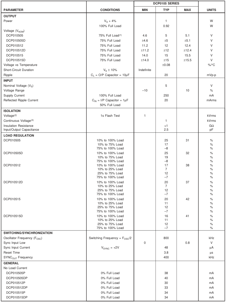
SPECIFICATIONS
At TA = +25°C, VS = +5V, unless otherwise specified.
Page 3
SPECIFICATIONS (CONT)
At TA = +25°C, VS = +5V, unless otherwise specified.
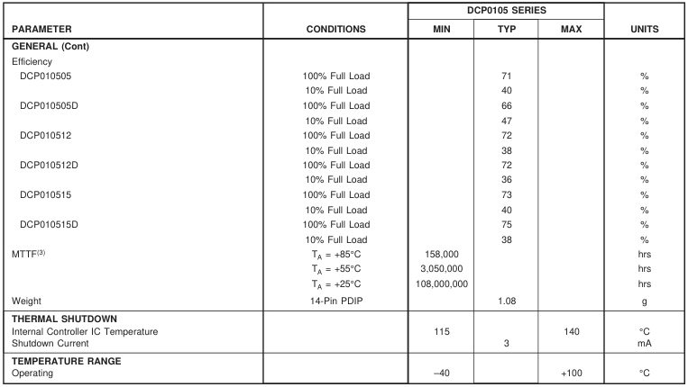
NOTES: (1) 100% load current = 1W/VNOM typical. (2) Rated working voltage = 130Vrms (IEC950 Convention). (3) Life test data.
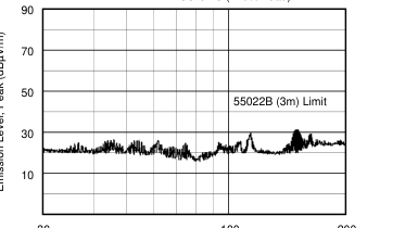
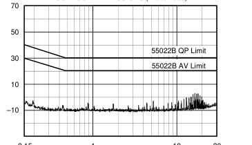
EMC SPECIFICATIONS Specifications and Related Documents The DCP010505 was tested to and complied with the limits of the following EMC specifications: prEN55022 (1992)
Conducted RF emission, telecomm lines. Limits and methods of measurement of radio interference characteristics of information technology equipment.
EN55022 (1995)
Electromagnetic compatibility. Basic immunity standard. Radiated RF immunity.
ENV50140 (1993)
Electromagnetic compatibility. Basic immunity standard. Conducted RF immunity.
ENV50141 (1993)
EN61000-4-2 (1995) Electromagnetic compatibility, Part 4. Testing and measurement techniques, Section 2. Electrostatic
discharge.
EN61000-4-4 (1995) Electromagnetic compatibility, Part 4. Testing and measurement techniques, Section 4. Electrical fast
transient bursts.
EN61000-4-8 (1994) Electromagnetic compatibility, Part 4. Testing and measurement techniques, Section 8. Power frequency
magnetic field immunity.
List of Tests The following is a list of tests which were required for compliance with the above specifications:
150kHz to 30MHz, power and output lines, Class B limits applying. DC/DC loads of
Conducted Emission Test
0%, 8%, and 120% applying. 30MHz to 1000MHz, Class B limits applying. DC/DC loads of 0%, 8%, and 120%
Radiated Emission Test
applying. 80MHz to 1000MHz, 10V/m, 1kHz 80% AM.
Radiated Immunity Test, Electric Field
900MHz, 10V/m, 200Hz 100% PM.
Radiated Immunity Test, Electric Field
4kV, HCP/VCP indirect discharge only.
Electrostatic Discharge Test
2kV power lines, 2kV signal lines.
Electrical Fast Transient Tests
150kHz to 80MHz, power and output lines, 10Vrms, 1kHz 80% AM.
Conducted RF Immunity Tests Radiated Immunity Test, Magnetic Field
50Hz, 30A/m
Page 4
PIN CONFIGURATION (Single)
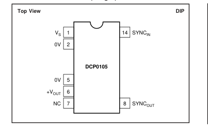
PIN DEFINITIONS (Single)
PIN CONFIGURATION (Dual)
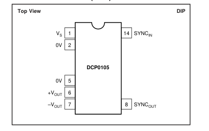
PIN DEFINITIONS (Dual)

The information provided herein is believed to be reliable; however, BURR-BROWN assumes no responsibility for inaccuracies or omissions. BURR-BROWN assumes no responsibility for the use of this information, and all use of such information shall be entirely at the user’s own risk. Prices and specifications are subject to change without notice. No patent rights or licenses to any of the circuits described herein are implied or granted to any third party. BURR-BROWN does not authorize or warrant any BURR-BROWN product for use in life support devices and/or systems.
Page 5
ABSOLUTE MAXIMUM RATINGS
Input Voltage .......................................................................................... 7V Storage Temperature ...................................................... –60°C to +150°C Lead Temperature (soldering, 10s) ................................................. 300°C
ORDERING INFORMATION
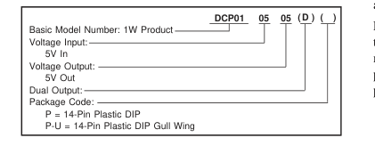
PACKAGE/ORDERING INFORMATION
ELECTROSTATIC
DISCHARGE SENSITIVITY
This integrated circuit can be damaged by ESD. Burr-Brown
recommends that all integrated circuits be handled with
appropriate precautions. Failure to observe proper handling
and installation procedures can cause damage. ESD damage can range from subtle performance degrada-
tion to complete device failure. Precision integrated circuits
may be more susceptible to damage because very small
parametric changes could cause the device not to meet its
published specifications.
| PRODUCT | PACKAGE | PACKAGE DRAWING NUMBER(1) | SPECIFIED TEMPERATURE RANGE | PACKAGE MARKING | ORDERING NUMBER(2) | TRANSPORT MEDIA |
| Single DCP010505 DCP010505 " DCP010512 DCP010512 " DCP010515 DCP010515 " Dual DCP010505D DCP010505D " DCP010512D DCP010512D " DCP010515D DCP010515D " | 14-Pin PDIP 14-Pin PDIP Gull Wing " 14-Pin PDIP 14-Pin PDIP Gull Wing " 14-Pin PDIP 14-Pin PDIP Gull Wing " 14-Pin PDIP 14-Pin PDIP Gull Wing " 14-Pin PDIP 14-Pin PDIP Gull Wing " 14-Pin PDIP 14-Pin PDIP Gull Wing " | 010-1 010-2 " 010-1 010-2 " 010-1 010-2 " 010-1 010-2 " 010-1 010-2 " 010-1 010-2 " | –40°C to +100°C –40°C to +100°C " –40°C to +100°C –40°C to +100°C " –40°C to +100°C –40°C to +100°C " –40°C to +100°C –40°C to +100°C " –40°C to +100°C –40°C to +100°C " –40°C to +100°C –40°C to +100°C " | DCP010505P DCP010505P-U " DCP010512P DCP010512P-U " DCP010515P DCP010515P-U " DCP010505DP DCP010505DP-U " DCP010512DP DCP010512DP-U " DCP010515DP DCP010515DP-U " | DCP010505P DCP010505P-U DCP010505P-U/700 DCP010505P DCP010505P-U DCP010505P-U/700 DCP010505P DCP010505P-U DCP010505P-U/700 DCP010505DP DCP010505DP-U DCP010505DP-U/700 DCP010512DP DCP010512DP-U DCP010512DP-U/700 DCP010515DP DCP010515DP-U DCP010515DP-U/700 | Rails Rails Tape and Reel Rails Rails Tape and Reel Rails Rails Tape and Reel Rails Rails Tape and Reel Rails Rails Tape and Reel Rails Rails Tape and Reel |
NOTES: (1) For detailed drawing and dimension table, please see end of data sheet, or Appendix C of Burr-Brown IC Data Book. (2) Models with a slash (/) are available only in Tape and Reel in the quantities indicated (e.g., /700 indicates 700 devices per reel). Ordering 700 pieces of DCP010505P-U/700 will get a single 700-piece Tape and Reel. For detailed Tape and Reel mechanical information, refer to Appendix B of Burr-Brown IC Data Book.
Page 6
TYPICAL PERFORMANCE CURVES (Common and DCP010505 Specific)
At TA = +25°C, VOUT nominal (VNOM) = +5V and VS = +5V, unless otherwise noted.
DCP010505 EFFICIENCY vs LOAD
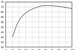
0 10 20 30 40 50 60 70 80 90 100
Full Load (%)
PEAK-TO-PEAK RIPPLE VOLTAGE vs LOAD
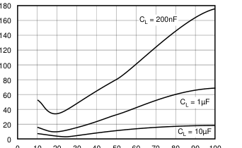
0 10 20 30 40 50 60 70 80 90 100
Load (%)
DCP010505 OUTPUT vs INPUT VOLTAGE (75% Load)
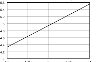
4.5 4.75
5 5.25 5.5
Input (V)
DCP010505 OUTPUT VOLTAGE vs LOAD
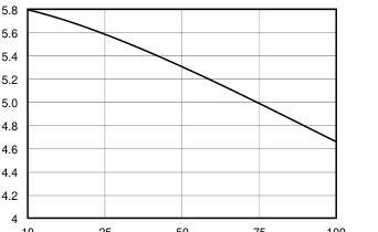
10 25 50 75 100
Full Load (%)
REFLECTED rms RIPPLE CURRENT vs LOAD
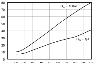
0 10 20 30 40 50 60 70 80 90 100
Load (%)
SWITCHING FREQUENCY vs SUPPLY VOLTAGE
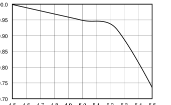
100.0
99.95
99.90
99.85
99.80
99.75
99.70 4.5 4.6 4.7 4.8 4.9 5.0 5.1 5.2 5.3 5.4 5.5
Input Supply Voltage (V)
Page 7
TYPICAL PERFORMANCE CURVES (Common and DCP010505 Specific, cont)
At TA = +25°C, VOUT nominal (VNOM) = +5V and VS = +5V, unless otherwise noted.
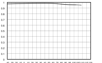
DCP010505 OUTPUT POWER vs TEMPERATURE
–40 –30 –20 –10 0 10 20 25 30 40 50 60 70 80 90 95 100 105 110 115 120
Temperature (°C)
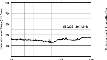
RADIATED EMISSIONS (8% Load)
30
100
200
Frequency (MHz)
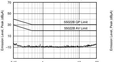
CONDUCTED EMISSIONS (8% Load)
0.15
1
10 30
Frequency (MHz)
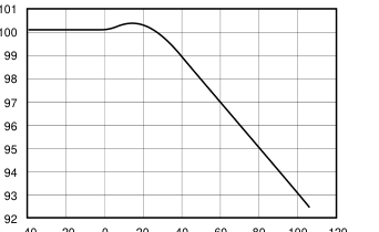
SWITCHING FREQUENCY vs TEMPERATURE
–40 –20
40 0 20 60 80 100 120
Temperature (°C)
RADIATED EMISSIONS (120% Load)
30
100
200
Frequency (MHz)
CONDUCTED EMISSIONS (120% Load)
0.15
1
10 30
Frequency (MHz)
Page 8
TYPICAL PERFORMANCE CURVES (DCP010505D Specific)
At TA = +25°C, VOUT nominal (VNOM) = ±5V and VS = +5V, unless otherwise noted.
DCP010505D OUTPUT vs INPUT VOLTAGE (75% Load)
4.5 4.6 4.7 4.8 4.9 5.0 5.1 5.2 5.3 5.4 5.5
Input Voltage (V)
DCP010505D LOAD BALANCE (+VOUT Load = 10%)
10
40
70
100
–VOUT Load (% of FL)
DCP010505D POWER vs TEMPERATURE
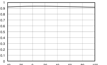
–40 –20 0 20 40 60 80 100
Temperature (°C)
DCP010505D OUTPUT VOLTAGE vs LOAD
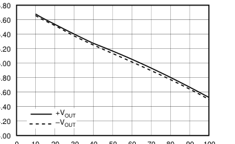
0 10 20 30 40 50 60 70 80 90 100
Load (%)
DCP010505D LOAD BALANCE (+VOUT Load = 100%)
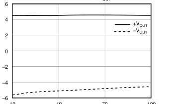
10
40
70
100
–VOUT Load (% of FL)
DCP010505D EFFICIENCY vs LOAD
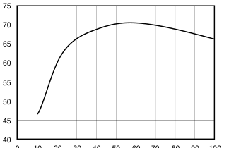
0 10 20 30 40 50 60 70 80 90 100
Load (%)
Page 9
TYPICAL PERFORMANCE CURVES (DCP010512 Specific)
At TA = +25°C, VOUT nominal (VNOM) = +12V and VS = +5V, unless otherwise noted.
DCP010512 OUTPUT vs INPUT VOLTAGE (75% Load)
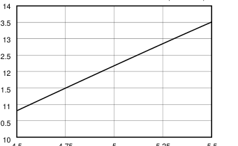
4.5 4.75
5 5.25 5.5
Input Voltage (V)
DCP010512 OUTPUT POWER vs TEMPERATURE
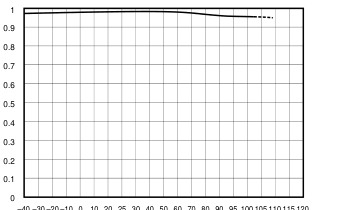
–40 –30 –20 –10 0 10 20 25 30 40 50 60 70 80 90 95 100 105 110 115 120
Temperature (°C)
DCP010512 OUTPUT VOLTAGE vs LOAD
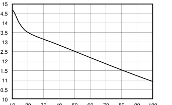
20 30 40 50 60 70 80 90 100 10
Load (%FL)
DCP010512 EFFICIENCY vs LOAD
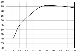
0 10 20 30 40 50 60 70 80 90 100
% of Full Load
Page 10
TYPICAL PERFORMANCE CURVES (DCP010512D Specific)
At TA = +25°C, VOUT nominal (VNOM) = ±12V and VS = +5V, unless otherwise noted.
DCP010512D OUTPUT vs INPUT VOLTAGE (75% Load)
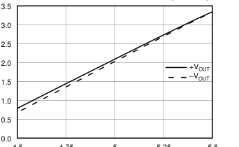
4.5 4.75
5 5.25 5.5
Input Voltage (V)
DCP010512D LOAD BALANCE (+VOUT Load = 10%)
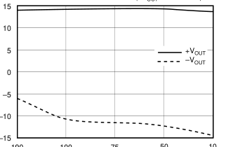
50 10
190 100 75 –VOUT Load (% of FL)
DCP010512D OUTPUT POWER vs TEMPERATURE
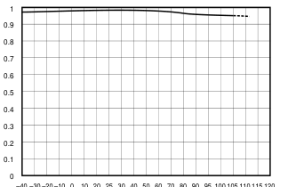
–40 –30 –20 –10 0 10 20 25 30 40 50 60 70 80 90 95 100 105 110 115 120
Temperature (°C)
DCP010512D OUTPUT VOLTAGE vs LOAD
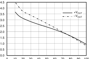
0 10 20 30 40 50 60 70 80 90 100
Load (% FL)
DCP0101512D LOAD BALANCE (+VOUT Load = 100%)
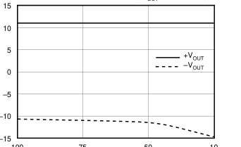
50
10
100
75 –VOUT Load (% of FL)
DCP010512D EFFICIENCY vs LOAD
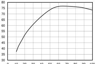
0 10 20 30 40 50 60 70 80 90 100
% of Full Load
Page 11
TYPICAL PERFORMANCE CURVES (DCP010515 Specific)
At TA = +25°C, VOUT nominal (VNOM) = +15V and VS = +5V, unless otherwise noted.
DCP010515 OUTPUT vs INPUT VOLTAGE (75% Load)
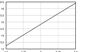
4.5 4.75
5 5.25 5.5
Input Voltage (V)
DCP010515 OUTPUT POWER vs TEMPERATURE
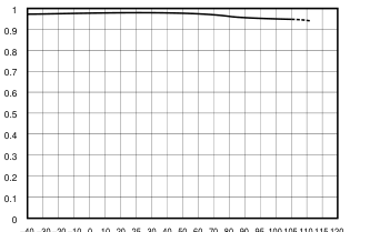
–40 –30 –20 –10 0 10 20 25 30 40 50 60 70 80 90 95 100 105 110 115 120
Temperature (°C)
DCP010515 OUTPUT VOLTAGE vs LOAD
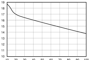
10 20 30 40 50 60 70 80 90 100
Load (% FL)
DCP010515 EFFICIENCY vs LOAD
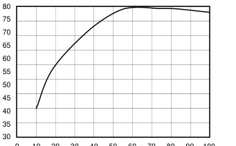
0 10 20 30 40 50 60 70 80 90 100
% of Full Load
Page 12
TYPICAL PERFORMANCE CURVES (DCP010515D Specific)
At TA = +25°C, VOUT nominal (VNOM) = ±15V and VS = +5V, unless otherwise noted.
DCP010515D OUTPUT vs INPUT VOLTAGE (75% Load)
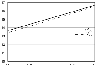
4.5 4.75
5 5.25 5.5
Input Voltage (V)
DCP010515D LOAD BALANCE (+VOUT Load = 10%)
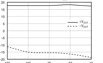
50 10
190 100 75 –VOUT Load (% of FL)
DCP010515D OUTPUT POWER vs TEMPERATURE
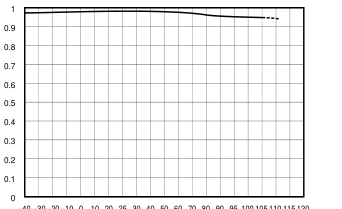
–40 –30 –20 –10 0 10 20 25 30 40 50 60 70 80 90 95 100 105 110 115 120
Temperature (°C)
DCP010515D OUTPUT VOLTAGE vs LOAD
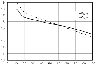
0 10 20 30 40 50 60 70 80 90 100
Load (% FL)
DCP010515D LOAD BALANCE (+VOUT Load = 100%)
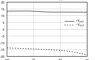
50
10
100
75 –VOUT Load (% of FL)
DCP010515D EFFICIENCY vs LOAD
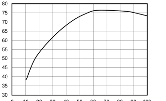
0 10 20 30 40 50 60 70 80 90 100
% of Full Load
Page 13
FUNCTIONAL DESCRIPTION
OVERVIEW
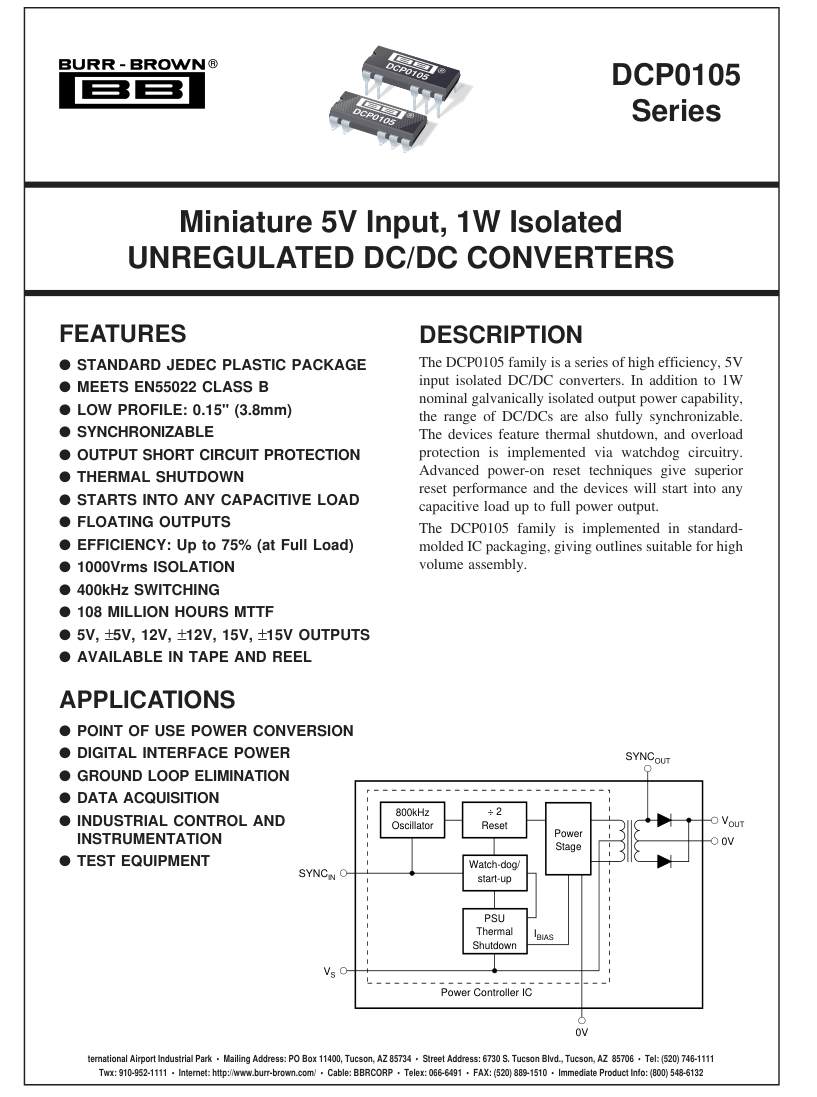
The DCP0105 offers 1W of unregulated output power from a 5V input source with a typical efficiency of up to 75%. This is achieved through highly integrated packaging technology and the implementation of a custom power stage and control IC.
POWER STAGE
This uses a push-pull, center-tapped topology switching at 400kHz (divide by 2 from 800kHz oscillator).
OSCILLATOR AND WATCHDOG
The on-board 800kHz oscillator provides the switching frequency via a divide by 2 circuit and allows synchronization via the SYNCIN pins. To synchronize any number of DCP0105 family of devices, simply tie the SYNCIN pins together (see the Synchronization section). The watchdog circuitry protects the DC/DC against a stopped oscillator and checks the oscillator frequency which will shut down the output stage if it drops below a certain threshold—i.e., it will be tri-stated after approximately 10µs.
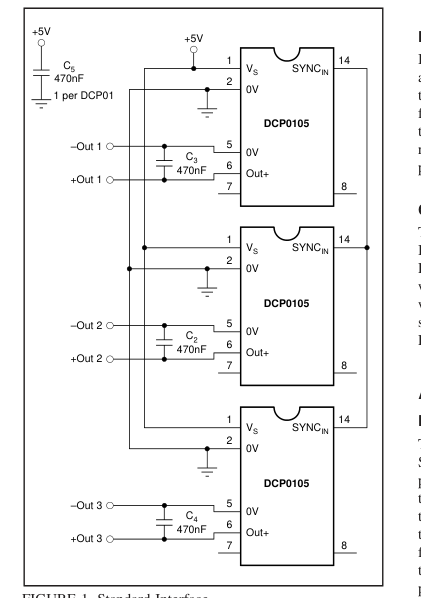
FIGURE 1. Standard Interface.
THERMAL SHUTDOWN
The DCP0105 is also protected by thermal shutdown. If the on-chip temperature reaches a predetermined value, the DC/ DC will shutdown. This effectively gives indefinite short circuit protection for the DC/DC.
SYNCHRONIZATION
Any number of DCP0105 devices can be synchronized by connecting the SYNCIN pins on the devices together (see Figure 1). All the DCP0105 devices will then selfsynchronize. This same synchronization method will apply to other VIN versions of the DCP01 family, allowing synchronization of various VOUT and VIN DC/DCs. Care must taken as synchronized DCP0105s will turn on simultaneously very quickly and draw 300mA each until each output capacitor is fully charged. This may exact a heavy demand on the input power supply. The SYNCOUT pin gives an unrectified 400kHz signal from the transformer. This can be used to set the timing of external circuitry on the output side. In noise sensitive
applications any pick-up from the SYNCOUT pin can be minimized by putting a guard ring round the pin (see Figure 7).
DIVIDE BY 2 RESET
Isolated DC/DC converter performance normally suffers after power reset. This is because a change in the steady state transformer flux creates an offset after power-up. The DCP01 family does not suffer from this problem. This is achieved through a patented(1) technique employed on the divide by 2 reset circuitry resulting in no change in output phase after power interruption.
CONSTRUCTION
The DCP0105’s basic construction is the same as standard ICs. There is no substrate within the molded package. The DCP0105 is constructed using an IC, rectifier diodes, and a wound magnetic toroid on a leadframe. As there is no solder within the package, the DCP0105 does not require any special PCB assembly processing. This results in an isolated DC/DC with inherently high reliability.
ADDITIONAL FUNCTIONS
DISABLE/ENABLE
The DCP0105 can be disabled or enabled by driving the SYNCIN pin with an open drain CMOS gate. If the SYNCIN pin is pulled LOW, the DCP0105 will disable. The disable time depends on the output loading but the internal shutdown takes up to 10µs. Making the gate open drain will re-enable the DCP0105. However, there is a trade-off in using this function; the DCP0105 quiescent current may increase and the on-chip oscillator may run slower. This degradation in performance is dependent on the external CMOS gate capacitance. Therefore, the smaller the capacitance, the lower the
Page 14
performance decrease. Driving the SYNCIN pin with a CPU type tri-state output, which has a low output capacitance, offers the lowest reduction in performance.
DECOUPLING
Ripple Reduction The high switching frequency of 400kHz allows simple filtering. To reduce ripple, it is recommended that 0.47µF capacitors are used on VS and VOUT (see Figure 2). Both outputs on dual output DCP0105 devices should be decoupled to pin 5. In applications where power is supplied over long lines and output loading is high, it may be necessary to use a 2.2µF capacitor on the input to insure startup. There is no restriction on the size of the output capacitor used to reduce ripple. The DCP0105 will start into any capacitive load. Low ESR capacitors will give the best reduction.
EXTERNAL SYNCHRONIZATION
The DCP0105 can be synchronized externally if required using a simple external interface. Figure 3 shows a universal
interface using a 4066 quad switch. The CTL and SYNCON pins are used to select external synchronization or selfsynchronization. This interface can also be used to stop (disable) the DCP0105.
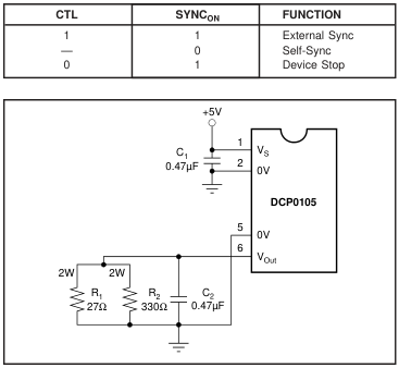
FIGURE 2. DCP010505 Fully Loaded.
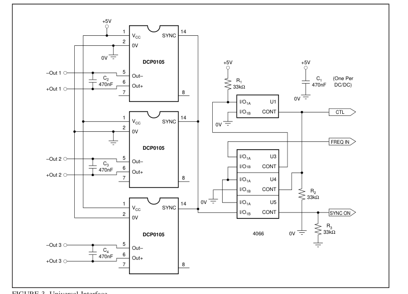
FIGURE 3. Universal Interface.
Page 15
Connecting the DCP0105 in Series Multiple DCP0105 isolated 1W DC/DC converters can be connected in series to provide non-standard voltage rails. This is possible by utilizing the floating outputs provided by the DCP0105’s galvanic isolation. Connect the positive VOUT from one DCP0105 to the negative VOUT (0V) of another (see Figure 4). If the SYNCIN pins are tied together, the self-synchronization feature of the DCP0105 will prevent beat frequencies on the voltage rails. The SYNC feature of the DCP0105 allows easy series connection without external filtering which is necessary in competing solutions. The outputs on dual output DCP0105 versions can also be
connected in series to provide 2 times the magnitude of VOUT (see Figure 5). For example, a dual 12V DCP010512D could be connected to provide a 24V rail.
Connecting the DCP0105 in Parallel If the output power from one DCP0105 is not sufficient, it is possible to parallel the outputs of multiple DCP0105s (see Figure 6). Again, the SYNC feature allows easy synchronization to prevent power-rail beat frequencies at no additional filtering cost.
THERMAL MANAGEMENT LAYOUT
To maximize the thermal performance of the DCP0105, taking more care in the PCB layout can provide the most efficient thermal dissipation paths from the DC/DC. The input controller IC and the rectifier diodes inside the DCP0105 are bonded directly onto the internal leadframe. The leadframe, being almost 100% copper, provides an excellent path for dissipated heat and does so significantly more efficiently than FR4 PCBs or ceramic substrates found in alternate packaging technology DC/DCs.
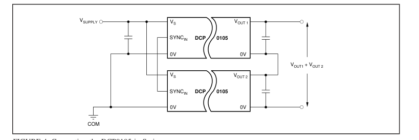
FIGURE 4. Connecting the DCP0105 in Series.

FIGURE 5. Connecting Dual Outputs in Series.
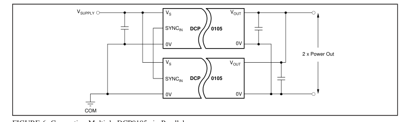
FIGURE 6. Connecting Multiple DCP0105s in Parallel.
Page 16
Most of the dissipated heat comes from input side common (pin 2). To a lesser extent, the +VOUT pin (pin 6) also dissipates heat from the package. In the layout shown in Figure 7, the large copper areas next to pins 2 and 6 will provide excellent heat dissipation paths. The tracking in Figure 7, shown in dotted lines, will provide shielding for the SYNCIN (pin 14) and SYNCOUT (pin 7) pins if necessary. As described earlier in the Disable/Enable section of this
dependent on the VIN of the DCP010505. With a VIN of 5.25V, the LP2986 LDO can deliver up to 165mA. The LP2986 LDO has a very low dropout voltage of typically less than 180mV, which allows us to deliver 4.75V guaranteed from a 5VOUT unregulated DC/DC. It also offers low output flagging and shutdown capability and is supplied in either MSOP-8 or SO-8 packages ensuring additional board area is minimal and low profile is maintained.
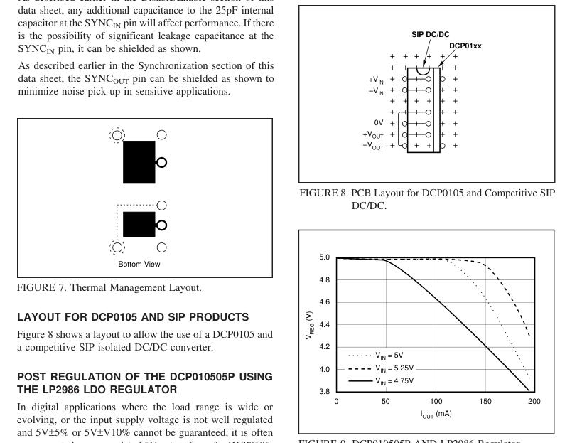
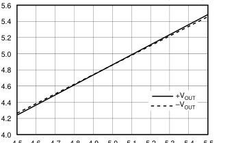
necessary to have a regulated 5V output from the DCP0105. It is possible to post regulate the 5VOUT DCP0105 and still guarantee a minimum VOUT of 4.75V. This still gives the benefits of isolation in reducing the power supply noise to 5V digital circuitry. By using an ultra-low dropout regulator (e.g., National Semiconductor’s LP2986IM-5.0) in series with the output of a 5VOUT DCP0105, it is possible to supply up to 100% load current (depending on VIN). Figure 9 shows the typical load current for the post-regulated 5VIN/5VOUT DCP010505. It is possible with a VIN of 5V to supply 130mA. Because of the 1:1 line regulation of the DCP0105, a 5% change in the input
will result in a 5% change in the output. Therefore, the amount of current that the LDO can deliver is strongly
FIGURE 9. DCP010505P AND LP2986 Regulator.
DCP01 AND LP2986 APPLICATION CIRCUIT
Figure 10 shows the LP2986 in series with the DCP010505 output. The 2.2µF capacitor on the input of the LP2986 and the 4.7µF capacitor on the output are the minimum recommended for good ripple reduction. Pin 7 on the LP2986 flags an error by going LOW if the output drops 5% below nominal.
Page 17
OTHER LDO REGULATORS
The SGS-Thomson L4940V5 LDO can also be used to post regulate the 5VOUT DCP010505 and can deliver a regulated minimum 4.75V up to 135mA. The 5VOUT DCP010505 can also be post regulated with the Micrel MIC5207 which offers up to 180mA output drive with a typical dropout voltage of 165mV at 150mA. The MIC5207 is available in a micro-sized SOT23-5 package which gives the minimum additional board area for post regulation.
PREDICTING OUTPUT VOLTAGE VERSUS LOAD
The Load Regulation specifications are calculated as follows:
| CONDITION | CALCULATION |
|---|---|
| 10% to 100% Load 10% to 25% Load 10% to 75% Load 75% to 100% Load | (V at 10% load – V at 100% load)/ V at 75% load OUT OUT OUT (V at 10% load – V at 25% load)/V at 25% load OUT OUT OUT (V at 10% load – V at 75% load)/V at 75% load OUT OUT OUT (V at 75% load – V at 100% load)/ V at 75% load OUT OUT OUT |
- To predict the output voltage at 100% load take the measured or specified voltage at 75% load and multiply by (1 + Load Reg 75% to 100%). For example a DCP010505P typical VOUT at 100% load will be 5V x (1 – 8%) = 4.6V.
- To predict the output voltage at 10% load take the measured or specified voltage at 75% load and multiply by (1 + Load Reg 10% to 75%). For example a DCP010505P typical VOUT at 10% load will be 5V x (1 + 17%) = 5.85V. 3. To predict the output voltage at 25% load on higher VOUT versions take the measured or specified voltage at 75% load and multiply by (1 + Load Reg 25% to 75%). For example a DCP010512P typical VOUT at 25% load will be 12V x (1 + 12%) = 13.4V. To then estimate the voltage at 10% load take the previously calculated VOUT at 25% load and multiply by (1 + Load Reg 10% to 25%). In this case the typical VOUT at 10% load will be 13.4V x (1 + 7%) = 14.3V.
To obtain predictions for loads other than those specified assume the VOUT versus load characteristic is linear between the load points and calculate accordingly. The 10% to 100% load specification guarantees the maximum voltage excursion for any load between 10% to 100% with respect to VOUT at 75% load. The above does not take into consideration line regulation and assumes a nominal input voltage. The 1:1 line regulation of the DCP01 family means that a percentage change in the input will give a corresponding percentage change in the output.
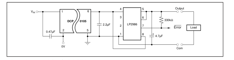
FIGURE 10. Post Regulation of DCP010505P.
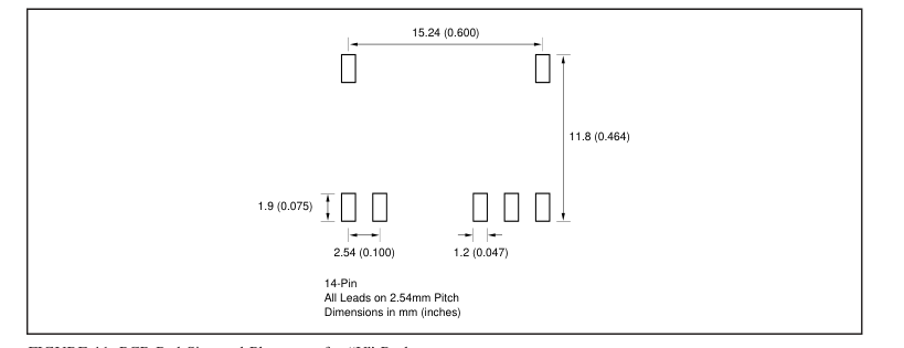
FIGURE 11. PCB Pad Size and Placement for “U” Package.