
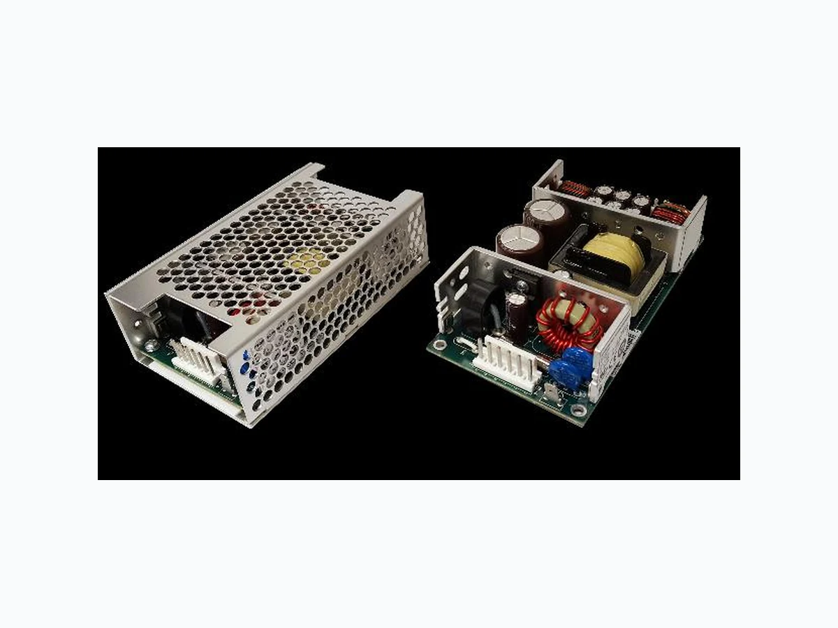
DC1-80 IPDPOWER
Document overview
- Manufacturer or author: Provided By www.digicamel.com(free datasheet download site)
- PDF pages: 2
Technical content
80 WATTS
FEATURES: CHASSIS/COVER OPEN FRAME SAFETY SPECIFICATIONS Underwriters Laboratories File E137708/E140259 UL 62368-1:2014, 2nd Edition CAN/CSA-C22.2 No. 62368-1-14 AAMI/ANSI ES60601-1:2005/(R) 2012 CAN/CSA-C22.2 No. 60601-1:2014 CB Reports/Certificates (including all National and Group Deviations) IEC 62368-1:2014, 2nd Edition IEC 60601-1:2005/A1:2012 TUV SUD America EN 62368-1:2014, 2nd Edition EN 60601-1:2006/A1:2013 RoHS Directive (Recast) (2015/863/EU of March 2015) Restriction of the Use of Certain Hazardous Substances in EEE Regulations 2012 SI No. 3032 + 2019 SI No.492 MODEL LISTING MODEL OUTPUT 1 OUTPUT 2 OUTPUT 3 OUTPUT 4 DC1-80-4003 +5V/6A -5V/5A +12V/2A -12V/2A DC1-80-4004 +5V/6A -5V/5A +15V/2A -15V/2A DC1-80-4005 +5V/6A +24V/2A +12V/2A -12V/2A DC1-80-4006 +5V/6A +24V/2A +15V/2A -15V/2A DC1-80-3001 +5V/6A +12V/2A -12V/2A DC1-80-3002 +5V/6A +15V/2A -15V/2A DC1-80-2001 +5V/6A +12V/4A DC1-80-2002 +5V/6A +24V/2A DC1-80-2004 +15V/3A -15V/3A DC1-80-1001 5V/16A DC1-80-1002 12V/6.7A DC1-80-1003 15V/5.3A DC1-80-1004 24V/3.3A DC1-80-1005 28V/2.9A DC1-80-1006 36V/2.2A DC1-80-1007 48V/1.7A
ORDERING INFORMATION
Consult factory for alternate output configurations. Consult factory for positive, negative or floating outputs. Please specify the following optional features when ordering: CH - Chassis I/O - Isolated Outputs CO - Cover TS - Terminal Strip DC1-80 OUTPUT SPECIFICATIONS Total Output Power at 50°C (1) 60W Singles Convection Cooled 50W Multi’s Convection Cooled (See Derating Chart) 80W 300LFM Forced-Air Cooled (12) Output Voltage Centering (5) Output 1: 0.5% (All outputs at 50% load) Output 2: 5.0% Output 3: 5.0% Output 4: 5.0% Output Voltage Adjust Range Output 1: 95 - 105% Load Regulation (5) Output 1: 0.5% (10-100% load change) Output 2: 5.0% Output 3: 5.0% Output 4: 5.0% Source Regulation Outputs 1 – 4: 0.5% Cross Regulation Outputs 2 – 4: 5.0% Output Noise (6) Outputs 1 – 4: 1.0% or 100mV, whichever is greater Turn on Overshoot 1% Transient Response Output recovers to within 1% of initial set point due to a 50-100-50% step load change, 1ms maximum, 4% maximum deviation. Output Overvoltage Protection Output 1: 110% to 150%, Latching Output Overpower Protection 110-150% rated Pout, cycle on/off, auto recovery Start Up Time 1 Second Output Rise Time 25-50ms typical Minimum Load (5) A minimum load of 10% is required on each output. INPUT SPECIFICATIONS Input Voltage Range 9-18 VDC Input Under-Voltage Lockout Turn-On Voltage 8.5-8.9 VDC Turn-Off Voltage 7.0-8.5 VDC Input Overvoltage Shutdown 19.0-21.0 VDC Input Protection Internal 15 A fuse Reflected Ripple Current 1% Efficiency 82% Typ., Full Power, (1002), varies by model ENVIRONMENTAL SPECIFICATIONS Ambient Operating 0C to + 70C Temperature Range Derating: See Power Rating Chart Ambient Storage Temp. Range - 40C to + 85C Temperature Coefficient Outputs 1 – 4: 0.02% /C Altitude 3,000m ASL – Operating – Medical 60601-1 5,000m ASL – Operating – ITE/AV – 62368-1 12,192m ASL – Non-Operating GENERAL SPECIFICATIONS Means of Protection Primary to Secondary 2MOPP (Means of Patient Protection) Primary to Ground 1MOPP (Means of Patient Protection) Secondary to Ground Operational Insulation(Consult factory for 1MOPP) Dielectric Strength(7, 8) Reinforced Insulation 4242 VDC, Primary to Secondary Basic Insulation 2121 VDC, Primary to Ground Operational Insulation 707 VDC, Secondary to Ground Power Good Signal(11) Logic high with input voltage above Vin min. Remote Sense (singles only)(9) 250mV compensation of output cable losses Mean-Time Between Failures 200,000 Hours min., MIL-HDBK-217F, 25° C, GB Weight 0.60 Lbs. Open Frame 1.00 Lbs. Chassis and Cover EMC SPECIFICATIONS Electrostatic Discharge EN61000-4-2 8KV contact/ 15KV air discharge A Surge Immunity EN61000-4-5 2KV line to earth/ 1KV line to line A All specifications are maximum at 25°C/80W unless otherwise stated, may vary by model and are subject to change without notice.
- Compact 2.5" x 4.5" x 1.2" Size
- 3 Year Warranty
- 9-18 VDC Input
- One to Four Outputs
- 4242VDC Reinforced Insulation
- Under/Overvoltage Lockout
- Pin Compatible with REL-70 Series
- IEC 60601-1 3rd ed. Medical Cert.
- IEC 62368-1 2nd ed. Certification
- 0-70°C Operating Temperature
- RoHS Compliant
- Optional Chassis/Cover
- Power Good Signal INTEGRATED POWER DESIGNS 300 Stewart Road ■ Wilkes-Barre, PA 18706 ■ Phone: (570) 824-4666 ■ Fax: (570) 824-4843 ■ Email: sales@ipdpower.com ■ Web: www.ipdpower.com
Output Power (Watts) Ambient Temperature (C) Maximum Output Power vs. Ambient Temperature ( A ) ( E ) ( B ) ( C , D ) DC1-80 SERIES MECHANICAL SPECIFICATIONS APPLICATIONS INFORMATION 1. Each output can deliver its rated current but total output power must not exceed 80W or as determined by the cooling requirements. 2. Generally, adequate cooling is provided when semiconductor case temperatures do not exceed 70°C rise and transformer temperature does not exceed 60°C rise at any specified ambient temperature. 3. Sufficient area must be provided around power supply to allow natural movement of air to develop in convection-cooled applications. 4. This product is intended for use as a professionally-installed component within information technology, industrial, and medical equipment and is not intended for stand-alone operation. 5. A minimum load of 10% is required on each output to ensure specified centering and regulation of each output. 6. Peak-to-Peak output ripple and noise is measured directly at the output terminals of the power supply, without the use of the probe ground lead or retractable tip (tip-and-barrel method), 20 MHz bandwidth. 7. This product was type-tested and safety-certified using the dielectric strength test voltages listed in Table 6 of IEC 60601-1:2005. In consideration of Clause 8.8.3, care must be taken to insure that the voltage applied to a reinforced insulation does not overstress different types and levels of insulation. Primary and secondary-to-ground capacitors may need to be disconnected prior to performing a dielectric strength test on the power supply or the end product. It is highly recommended that the DC test voltages listed in DVB.1, Annex DVB of UL 60601-1 1st Edition are not exceeded during a production-line dielectric strength test of the assembled end product. Please consult factory for further information. 8. This power supply has been safety-approved and final-tested using a DC dielectric strength test. Please consult factory before performing an AC dielectric strength test. 9. Remote-Sense terminals may be used to compensate for cable losses up to 250mV (single output models only). The use of a twisted pair, decoupling capacitors and an appropriately-rated low-impedance capacitor connected across the load will increase noise immunity. 10. Maximum screw penetration into bottom chassis mounting holes is 0.100 inches. Maximum screw penetration into side chassis mounting holes is 0.250 inches. 11. Power good feature provides a logic-high signal from an open collector transistor when DC input reaches minimum operating voltage. 12. 300LFM minimum of airflow must be maintained one inch above all points of top-side components or cover when forced-air cooling is required. CONNECTOR SPECIFICATIONS P1 DC Input 0.156 friction lock header mates with TE Connectivity 770849-6 or equivalent crimp terminal housing with TE Connectivity 3-640707-1 or equivalent crimp terminal. P2 DC Output 0.156 friction lock header mates with TE Connectivity 770849-8 or equivalent crimp terminal housing with TE Connectivity 3-640707-1 or equivalent crimp terminal. G Ground 0.187 quick disconnect terminal. P3 Power Good /Sense (Single) 0.100 breakaway header mates with Molex 22-55-2061 or equivalent crimp terminal housing with Molex type 71851 or equivalent crimp terminal. P3 Power Good (Multiple) 0.100 breakaway header mates with Molex 50-57-9002 or equivalent crimp terminal housing with Molex type 71851 or equivalent crimp terminal. MAXIMUM OUTPUT POWER vs. AMBIENT TEMPERATURE OUTPUT RATING: (A) 80 Watts Max. Output Power with 300 LFM Forced Air. Open Frame or with Chassis/Cover. (B) 60 Watts Max. Output Power Convection Cooled. Open Frame or with Chassis. Singles. (C) 50 Watts Max. Output Power Convection Cooled. Open Frame or with Chassis. Multi’s. (D) 50 Watts Max. Output Power Convection Cooled with Chassis/Cover. Singles. (E) 40 Watts Max. Output Power Convection Cooled with Chassis/Cover. Multi’s. INTEGRATED POWER DESIGNS 300 Stewart Road ■ Wilkes-Barre, PA 18706 ■ Phone: (570) 824-4666 ■ Fax: (570) 824-4843 ■ Email: sales@ipdpower.com ■ Web: www.ipdpower.com REV. C 10/06/2022