
DATASHEET SEARCH SITE
Document overview
- Manufacturer or author: Provided By www.digicamel.com(FREE DATASHEET DOWNLOAD SITE)
- PDF pages: 2
Technical content
Features
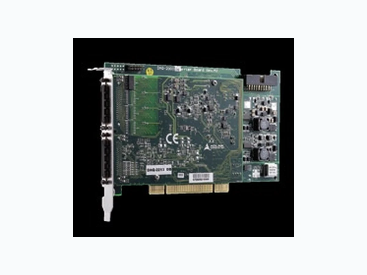
■ Supports a 32-bit 3.3 V or 5 V PCI bus (DAQ-2213, DAQ-2214) ■ x1 lane PCI Express® Interface (DAQe-2213, DAQe-2214) ■ Onboard 1 k-sample A/D FIFO ■ Bipolar or unipolar analog input ranges ■ Programmable gains: x1, x2, x4, x8 ■ 512-configuration channel gain queue ■ Scatter-gather DMA ■ 2-CH 12-bit multiplying analog outputs with waveform generation (DAQ/DAQe-2214) ■ Onboard 1 k-sample D/A FIFO (DAQ-2214, DAQe-2214) ■ 24-CH TTL digital input/output ■ 2-CH 16-bit general-purpose timer/counter ■ Analog and digital triggering ■ Fully auto calibration ■ Multiple cards synchronization through SSI (System Synchronization Interface) bus ■ Operating Systems
- Windows 7/Vista/XP/2000/2003 Server
- Linux ■ Recommended Software
- AD-Logger
- VB.NET/VC.NET/VB/VC++/BCB/Delphi
- DAQBench ■ Driver Support
- DAQPilot for LabVIEW™
- DAQ-MTLB for MATLAB
- D2K-DASK for Windows
- D2K-DASK/X for Linux DAQ/DAQe-2213/2214 T erminal Boards & Cables ■ DIN-68S-01 T erminal Board with One 68-pin SCSI-II Connector and DIN-Rail Mounting (Cables are not included.) ■ ACL-10568-1 68-pin SCSI-VHDCI cable (mating with AMP-787082-7), 1 M * For more information on mating cables, please refer to P2-61/62. SSI Bus Cables (DAQ/DAQe-2214) (for multiple cards synchronization) ■ ACL-SSI-2 SSI Bus cable for 2 devices ■ ACL-SSI-3 SSI Bus cable for 3 devices ■ ACL-SSI-4 SSI Bus cable for 4 devices T erminal board DIN-68S-01 & 68-Pin SCSI-VHDCI cable ACL-10568-1 Pin Assignment Connector CN1 AI0 (AIH0) AI1 (AIH1) AI2 (AIH2) AI3 (AIH3) AI4 (AIH4) AI5 (AIH5) AI6 (AIH6) AI7 (AIH7) NC NC NC NC NC NC NC NC AISENSE NC NC NC NC NC NC NC NC NC NC NC NC NC NC NC NC EXTATRIG (AIL0) AI8 (AIL1) AI9 (AIL2) AI10 (AIL3) AI11 (AIL4) AI12 (AIL5) AI13 (AIL6) AI14 (AIL7) AI15 NC NC NC NC NC NC NC NC AIGND NC NC NC NC NC NC NC NC NC NC NC NC NC NC NC NC AIGND Pin Assignment Connector CN2 NC / DA0OUT* NC / DA1OUT* NC / AOEXTREF* NC DGND RESERVED / EXTWFTRIG* EXTDTRIG SSHOUT RESERVED RESERVED RESERVED / AFI1* AFI0 GPTC0_SRC GPTC0_GATE GPTC0_UPDOWN GPTC0_OUT GPTC1_SRC GPTC1_GATE GPTC1_UPDOWN GPTC1_OUT EXTTIMEBASE PB7 PB5 PB3 PB1 PC7 PC5 DGND PC3 PC1 PA7 PA5 PA3 PA1 AOGND* / NC AOGND* / NC AOGND* / NC NC DGND DGND DGND DGND DGND DGND DGND DGND DGND DGND DGND DGND DGND DGND DGND DGND DGND PB6 PB4 PB2 PB0 PC6 PC4 DGND PC2 PC0 PA6 PA4 PA2 PA0 * Note: Analog output related pins on the DAQ/DAQe-2214 SSI bus cable for multiple card synchronization for DAQ/DAQe-2000 series DAQe-2213 / 2214 DAQ-2213/2214 16-CH 16-Bit 250 kS/s Low-Cost Multi-Function DAQ Cards
Software & Utilities Fanless Embedded Computers DAQ PXI/PXIe Modular Instruments GPIB & Bus Expansion Motion Control Real-time Distributed I/O PAC Remote I/O Communi- cations Vision cPCI & Industrial Computers 2-24www.adlinktech.com High-Performance DAQ Ordering Information / Quick Selection Guide Model Name Analog Input Analog Output DIO Timer/Counter No. of channels Resolution Sampling rate Input range No. of channels Resolution Sampling rate No. of channels No. of channels DAQ/DAQe-2213 8 DI/16 SE 16 bits 250 kS/s ±1.25 V to ±10 V - - - 24-CH 8255 PIO 2-CH, 16-bit DAQ/DAQe-2214 8 DI/16 SE 16 bits 250 kS/s ±1.25 V to ±10 V 2 12 bits 1 MS/s 24-CH 8255 PIO 2-CH, 16-bit Specifications Model Name DAQ/DAQe-2213 DAQ/DAQe-2214 *Gain = 1, 2, 4, 8 Analog Input Resolution Number of channels Channel gain queue size Maximum update rate Programmable gain Bipolar input ranges Unipolar input ranges Offset error Gain error Input coupling Overvoltage protection Input impedance CMRR (gain = 1) Settling time -3 dB small signal bandwidth (@Bipolar +/-10V Gain=1) Trigger sources Trigger modes FIFO buffer size Data transfers Analog Output Number of channels Resolution Output ranges Maximum update rate Slew rate Settling time Offset error Gain error Driving capacity Stability Trigger sources Trigger modes FIFO buffer size Data transfers Digital I/O Number of channels Compatibility Data transfers General-Purpose Timer/Counter Number of channels Resolution Compatibility Base clock available Auto Calibration Onboard reference Temperature drift Stability General Specifications Dimensions Connector Operating temperature Storage temperature Humidity Power requirements 16 bits, no missing codes 16 single-ended or 8 differential (software selectable per channel) 512 250 kS/s 1, 2, 4, 8 ±1 mV ±0.06% of FSR DC Power on: Continuous ±30 V, Power off: Continuous ±15 V
1 GΩ /100 pF
4 μs to 0.01% error 600 kHz (@Bipolar +/-10V Gain=1) Software, external digital/analog trigger, SSI bus Pre-trigger, post-trigger, middle-trigger, delay-trigger, and repeated trigger 1 k samples Polling, scatter-gather DMA - 2 voltage outputs - 12 bits - 0-10 V, ±10 V, 0-AOEXTREF , ±AOEXTREF - 1 μs - 20 V / μs - 3 μs to ±0.5 LSB accuracy - ±2 mV - ±0.04% of max. output - ±5 mA - Any passive load, up to 1500 pF - Software, external digital/analog trigger, SSI bus - Post-trigger, delay-trigger, and repeated trigger - 1 k samples - Programmed I/O, scatter-gather DMA 24-CH 8255 programmable input/output
5 V/TTL
40 MHz, external clock up to 10 MHz
+5 V ±2 ppm/˚C ±6 ppm/1000 Hrs 175 mm x 107 mm (not including connectors) (DAQ-2213/2214) 168 mm x 107 mm (not including connectors) (DAQe-2213/2214) 68-pin VHDCI female x 2 0 to 55˚C -20 to 70˚C 5 to 95%, non-condensing +5 V 1.2 A typical (DAQ-2213) +5 V 1.2 A typical (DAQ-2214)