
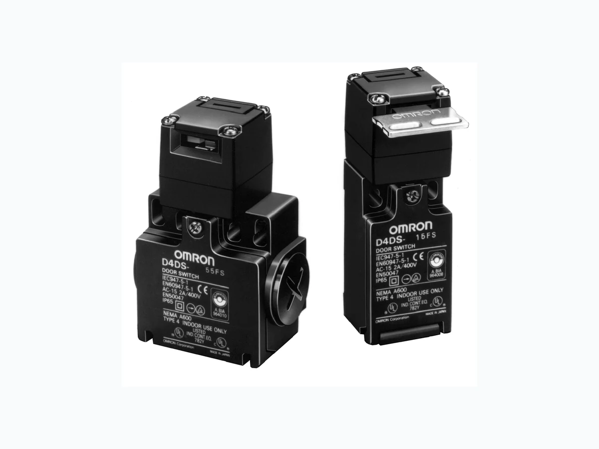
D4DS ETC1
Document overview
- Manufacturer or author: Provided By www.digicamel.com(FREE DATASHEET DOWNLOAD SITE)
- PDF pages: 12
Technical content
Compact Safety Switch Saves Space and is Ideal for a Variety of Doors H Conforms to EN (TÜV) standards. (positive opening mechanism i si n d i c a t e do nt h e switch) H Wide standard operating temperature range: - -30 to 70°C H Double-insulation structure (with mark) requires no grounding terminals H Five-direction Operation Key H Approved by UL, CSA, BIA and SUVA standards H Standards and EC Directives:
- Conforms to the following EC Directives: Machinery Directive Low Voltage Directive EN50047 EN1088 H Approved Standards Agency Standard File No. TÜV Rheinland EN60947-5-1 R9551708 (Positive opening: approved) UL (see note) UL508 CSA C22.2 No.14 E76675 BIA GS-ET-15 1-conduit: 9509915 2-conduit: 9509913 SUVA SUVA 1-conduit: 6010Z 2-conduit: 6011Z Note: CSA C22.2 No. 14 compliance was verified and approved by UL (Marked with E u
Ordering Information
- Conduit size/type 1: Pg13.5 (1-conduit, European type) 2: G1/2 (1-conduit, Japanese type) 3: 1/2-14NPT (1-conduit, North American type) 5: Pg13.5 (2-conduit) (1-conduit, European type) 6: G1/2 (2-conduit Japanese type) 2. Built-in Switch 5: 1NC/1NO (Slow-action) A: 2NC (Slow-action) 3. Head Mounting Direction F: Four mounting directions pos- sible (Front-side mounting at shipping) 1. Operation Key Type 1: Horizontal mounting 2: Vertical mounting 3: Adjustable mounting (Horizontal) 5: Adjustable mounting (Horizontal/ Vertical) D4DS-Kj Operation Key D4DS-jjjS 123 Note: An order for the head part or the switch part alone cannot be accepted. The Operation Key is sold separately. J SWITCHES Description Part number Appearance Conduit size/type 1NC/1NO (Slow-action) 2NC (Slow-action) 1-conduit Pg13.5 (European) D4DS-15FS D4DS-1AFS G1/2 (Japanese) D4DS-25FS D4DS-2AFS 1/2-14NPT (North American) D4DS-35FS D4DS-3AFS 2-conduit Pg13.5 (European) D4DS-55FS D4DS-5AFS G1/2 (Japanese) D4DS-65FS D4DS-6AFS J OPERATION KEYS (ORDER SEPARATELY) Type Part number Horizontal mounting D4DS-K1 Vertical mounting D4DS-K2 Adjustable mounting (Horizontal) D4DS-K3 Adjustable mounting (Horizontal/Vertical) D4DS-K5
J APPROVED STANDARD RATINGS TÜV (EN60947-5-1) Utilization category AC-15 Rated operating current (Ie) 2A Rated operating voltage (Ue) 400 V Note: Use a 10-A fuse type gl or gG as a short-circuit protection device that conforms to IEC269. UL (UL508/CSA C22.2 No.14) A600 Rated voltage Carry current Current Volt-amperesy Make Break Make Break
120 VAC 10 A 60 A 6A 7,200 VA 720 VA
240 VAC 30 A 3A
480 VAC 15 A 1.5 A 600 VAC 12 A 1.2 A J CHARACTERISTICS Degree of protection (see note 1) IP65 (EN60947-5-1) Life expectancy (see note 2) Mechanical: 1,000,000 operations min. Electrical: 150,000 operations min. Operating speed 0.1 m/s to 0.5 m/s Contact gap 2x2 . 0m mm i n . Operating frequency 30 operations/minute min. Positive opening force (see note 3) 58.84 N min. Positive opening travel (see note 3) 10 mm min. Insulation resistance 100 MΩ min. (at 500 VDC) between terminals of same polarity, between terminals of different polarity, between each terminaland ground, and between each terminal and non-current-carrying metal part Contact resistance 25 mΩ max. (initial value) Dielectric strength Uimp 4 kV between terminals of same polarity, between terminals of different polarity, and between each terminal and non-current-carrying metal part (EN60947-5-1) Rated insulation voltage (Ui) 400 V (EN60947-5-1) Conditional short-circuit current 100 A (EN60947-5-1) Short-circuit protective device (SCPD) 10 A, fuse type gI or gG (IEC269) Switching overvoltage 1,500 V max. (EN60947-5-1) Pollution degree (operating environment) 3 (EN60947-5-1) Conventional enclosed thermal current the)
10 A (EN60947-5-1)
Protection against electric shock Class II (double insulation) Vibration resistance Malfunction: 10 to 500 Hz, 0.65-mm single amplitude with an imposed acceleration of 100 m/s2 max. Shock resistance Destruction: 1,000 m/s2 min. Malfunction: 300 m/s2 min. Ambient temperature Operating: - -30°Ct o7 0°C (with no icing) Ambient humidity Operating: 95% max. Weight Approx. 76 g (for D4DS-15FS) Note: 1. Although the Switch casing resists dust, oil, and water, make sure that the keyhole on the head is free from dust, oil, water, and chemical, or the D4DS may wear out, break, or malfunction. 2. Life expectancy values are calculated at an operating temperature of 5°Ct o3 5°C, and an operating humidity of 40% to 70%. Contact your OMRON sales representative for more detailed information on other operating environments. 3. These figures are minimum requirements for safe operation.
J OPERATING CHARACTERISTICS 1-Conduit/2-Conduit Models Model D4DS-jjjS Operating force (extraction) 14.71 N Release force (insertion) 29.42 N Pretravel 6±3m m Total travel (reference value) 28 mm Min. positive opening force (see note) 58.84 N Min. positive opening stroke (see note) 10 mm Note: Make sure that the positive opening stroke is at least 16 mm in order to use the D4DS safely. Nomenclature Operation Key The dedicated key prevents operational mistakes and forci- bly separates the contacts. Head The head can be mounted in four directions. The Opera- tion Key can be inserted in five directions including the downward direction. Cover T h ec o v e r ,w i t hah i n g eo ni t sl o w e rp a r t ,c a nb eo p e n e d by removing the screw of the cover, which ensures ease of maintenance and wiring. Built-in Switch Has a positive opening mechanism which forcibly separates the NC contacts even if they are welded. The built-in switch incorporates a pair each of NC contacts and NO contacts or two pairs of NC contacts. Conduit Wide switch variations. Pg13.5: 1-conduit, 2-conduit models G1/2: 1-conduit, 2-conduit models 1/2-14NPT: 1-conduit models Oil Seal The plunger has an O ring. The switch casing ensures IP65 (except the keyhole, which ensures IP00). Use the D4DS in places where the keyhole is free from oil and metal chips. Note: The housing and head of the D4DS are made of synthetic resin. If high mechanical durability is required, use the D4BS Safety Door Switch.
J CONTACT FORM(DIAGRAMS SHOW STATE WITH KEY INSERTED) Model Contact Diagrams Remarks D4DS-j5jS 1NC/1NO 11 12 23 24 Zb 11 - 12 23 - 24 Stroke ON Operation Key insertion comple- tion position Pull-out completion position Only NC contact 11-12 has an approved positive opening mechanism. The terminals 11-12 and 23-24 can be used as unlike poles. D4DS-jAjS 2NC Zb 11 - 12 21 - 22 Stroke ON Operation Key insertion comple- tion position Pull-out completion position NC contacts 11-12 and 21-22 have an approved positive opening mechanism. The terminals 11-12 and 23-24 can be used as unlike poles. Note: Terminals are numbered according to EN50013 and contacts are marked according to EN60947-5-1. J POSITIVE OPENING MECHANISM 1NC/1NO Contact (Slow-Action) 2NC Contact (Slow-Action) Contact spring Return spring Fixed contact (NC) Movable contact Plunger Fixed contact (NO) Contact spring Return spring Fixed contact (NC) Movable contact Plunger Only the NC contacts have a positive opening function. When metal deposition occurs, the contacts are separated from each other by pushing in the plunger. Conforms to EN60947-5-1 Positive Opening Both NC contacts incorporate a positive opening function. When metal deposition occurs, the contacts are separated from each other by pushing in the plunger. Conforms to EN60947-5-1 Positive Opening Note: The switches are marked with indicating approval for the positive opening mechanism.
Unit: mm (inch) Note: 1. Unless otherwise specified, a tolerance of±0.4 mm applies to all dimensions. 2. The conduit thread varies with the model as follows: Conduit thread Model Pg13.5 D4DS-1jjS/-5jjS G1/2 D4DS-2jjS/-6jjS 1/2-14NPT D4DS-3jjS Conduit opening J SWITCHES 1-Conduit Models D4DS-1jjS D4DS-2jjS D4DS-3jjS 2-Conduit Models D4DS-5jjS D4DS-6jjS R2.15±0.05 mounting holes depth: 5 Two, 4+0.15 0 dia. holes 30 x 30 30 x 30 Cap depth: 5 Two, 4+0.15 0 dia. holes56 max. R2.15±0.05 mounting holes Red Black Red Black Conduit opening
Adjustable Mounting (Horizontal) D4DS-K3 Four, R2.15 Four, R2.15 9d i a . 8d i a .4.5 dia. Black Adjustable Mounting (Horizontal/Vertical) D4DS-K5 18° Two, M4 9±0.1 41±0.1 43±0.1 Mounting Holes Black Note: Each dimension has a tolerance of±0.4 mm unless otherwise specified.
J WITH OPERATION KEY INSERTED Horizontal Mounting D4DS-1jjS + D4DS-K1 D4DS-2jjS + D4DS-K1 D4DS-3jjS + D4DS-K1 D4DS-5jjS + D4DS-K1 D4DS-6jjS + D4DS-K1 Vertical Mounting D4DS-1jjS + D4DS-K2 D4DS-2jjS + D4DS-K2 D4DS-3jjS + D4DS-K2 D4DS-5jjS + D4DS-K2 D4DS-6jjS + D4DS-K2 D4DS-1jjS + D4DS-K3 D4DS-2jjS + D4DS-K3 D4DS-3jjS + D4DS-K3 D4DS-5jjS + D4DS-K3 D4DS-6jjS + D4DS-K3 44 to 46.5 Key insertion face Horizontal key insertion radius R ≧ 200 Permissible difference in center lines between the Operation Key and key hole. 44 to 46.5 Key insertion face Permissible difference in center lines between the Operation Key and key hole. Horizontal key insertion radius R ≧ 200 44 to 46.5 Key insertion face Horizontal key insertion radius R ≧ 200 Permissible difference in center lines between the Operation Key and key hole. 44 to 46.5 Key insertion face Permissible difference in center lines be- tween the Operation Key and key hole. Horizontal key insertion radius R ≧ 200 44 to 46.5 Key insertion face Horizontal key insertion radius R ≧ 200 Permissible difference in center lines between the Operation Key and key hole. 44 to 46.5 Key insertion face Permissible difference in center lines between the Operation Key and key hole. Horizontal key insertion radius R ≧ 200 D4DS-1jjS + D4DS-K5 D4DS-2jjS + D4DS-K5 D4DS-3jjS + D4DS-K5 D4DS-5jjS + D4DS-K5 D4DS-6jjS + D4DS-K5 51.9 to 54.4 Key insertion face Horizontal key insertion radius R ≧ 50 Permissible difference in center lines between the Operation Key and key hole. 51.9 to 54.4 Key insertion face Permissible difference in center lines between the Operation Key and key hole. Horizontal key insertion radius R ≧ 200 Red Black Red Black Red Black Red Black Adjustable Mounting (Horizontal/Vertical)Adjustable Mounting (Horizontal)
! CAUTION Do not remove the operation key from the door intentionally and insert it into the switch with the door open. The machine may start operating, and injury or death may be caused. Do not use metal connectors or conduits with this switch. Rigid connectors and conduits may damage the switch. The broken conduit hole may cause an electrical shock hazard. Install the operation key so thatit will not hit the operator when the door is open. If the D4DS is to be used as a switch in an emergency stop circuit or in a safety circuit for preventing accidents resulting in injuries or deaths, use NC contacts with a forced release mechanism and set the D4DS so that it will operate in positive opening mode. For safety, install the Switch and the Operation Key using one-way rotational screws or other similar means to prevent them from easily coming off. Protect the D4DS with an appropriate cover and post a warning sign near the D4DS in order to ensure the safety of the door. To prevent the D4DS from damage due to circuit short-circuiting, connect a fuse with a breaking current 1.5 to 2 times larger than the rated current of the D4DS in series to the D4DS. If the D4DS is used under EN-approved conditions, use a gI or gG 10-A fuse approved by IEC269. Mount with a Stopper Be sure to mount the D4DS with a stopper as shown in the following illustration. Do not use the casing of the D4DS as a stopper. Be sure to install the stopper so that the space “a” will be a maximum of 3 mm. Stopper Switch J CORRECT USE Operating Environment Do not use the D4DS in the following environments, or the D4DS may malfunction.
- Locations subject to significant temperature fluctuations
- Humid locations where there is a risk of condensation
- Locations subject to significant vibrations
- Locations subject to metal chips, oils, and chemicals inside a protective door Operation Key Be sure to use a special Operation Key only. Do not operate the D4DS with anything other than the special Operation Key, or the D4DS may break or the safety of the system may not be maintained. Do not impose excessive force on the Operation Key inserted into the D4DS or drop the D4DS with the Operation Key inserted, or the Operation Key may deform or break. Excessive force Drop Secure the Operation Key with screws so that the Operation Key cannot be removed easily. Refer toDimensions for the mounting dimensions of the Operation Key and properly mount the Operation Key so that the position and angle will be correct. Make sure that the Operation Key can be inserted correctly with a tolerance of±0.5 mm in the upward, downward, left, or right direction, or damage to the D4DS may occur. ±1m i n . ±1m i n .
Be sure to tighten each screw tothe appropriate tightening torque as shown below. 2 6 No. Type Torque 1 Terminal screw 0.59 to 0.78 NS m 2 Cover mounting screw 0.78 to 0.88 NS m 3 Head mounting screw 0.78 to 0.88 NS m
4 M4 switch mounting bolt
(see note 1) 0.49 to 0.69 NS m
5 Operation Key mounting
2.35 to 2.75 NS m 6 Connector 1.77 to 2.16 NS m 1.37 to 1.77 NS m (see note 2) 7 Cap screw 1.27 to 1.67 NS m Note: 1. Tighten each screw with a washer and use the ap- propriate tightening torque. 2. This force range applies to 1/2-14NPT. Mounting Switch Two, M4 Allen-head bolts with washers must be used in order to mount the D4DS securely. To mount the D4DS more securely, prepare two, 4 - -0.05/- -0.15dia. protruding portions with 4.8 mm maximum in height each as shown below and support the D4DS at a total of four points. Mounting Dimensions with Protruding Portions Standard Model Two-Conduit Model 4-- 0 . 0 5 -- 0 . 1 5dia. height, 4.8 max. 4-- 0 . 0 5 -- 0 . 1 5 dia. height, 4.8 max. Mounting hole Mounting surface Insertion hole for protrusions 4-- 0 . 0 5 -- 0 . 1 5dia. height, 4.8 max.
Two, M4 Operation Key Mounting Dimensions Horizontal/Vertical Mounting D4DS-K1 or D4DS-K2 Two, M4 Adjustable Mounting (Horizontal) D4DS-K3 Two, M4 9 ±0.1 41±0.1 43±0.1 Adjustable Mounting (Horizontal/Vertical) D4DS-K5 Securing the Door When the door is closed (with the Operation Key inserted), the door (or the Operation Key) may be pushed back across the set zone due to the door’s weight, the door cushion rubber, etc. If load is applied to the Operation Key, the door may fail to unlock. Secure the door with hooks so that it will remain within in the set zone. Set zone (0.5 to 3 mm) Operation Key Changes in Head Mounting Direction By removing the screws on the four corners of the head, the head can be reset in any of four directions. When changing the head mounting direction, make sure that the Operation Key is in the head. Make sure that no foreign materials penetrate through the mounting holes of the head. Internal screws of the head must not be removed, or the internal parts of the head may be lost or deformed. Dd i a . dz dia. dz dia.: 3.7 Dd i a . : 4 . 5 B: 7.0 L: 20.2 F: 7.7 I: 9.0 (mm) Wiring Do not connect lead wires directly to the terminals. Be sure to connect the lead wires through insulation tubes and crimp terminals., and tighten each terminal screw within an optimum torque range. The lead wires must be an AWG20 to A W G 1 4t y p e( i . e . ,0 . 5t o2 5m m 2 thick).
Tighten the connector to a torque of 1.8 to 2.2 NS m (1.37 to 1.77 NS m if it is a 1/2-14NPT). Excessive tightening torque may damage the casing. In order to continue satisfying IP65, apply sealing tape to the connector conduit. The diameter of the cable must be suited to the corresponding connector. Wire the crimp terminal as shown in the following diagram so that it will not come in contact with the case or cover. Properly attach the provided conduit cap to the unused conduit opening and securely tighten the cap screw within a torque range between 1.27 and 1.67 NS m when wiring the D4DS two-conduit model. Recommended Connector Size Manufacturer Model Suitable cable dia. G1/2 OMRON SC-6 7 . 5t o9 . 0m m LAPP (see note 1) ST-PF1/2 5360-1002 6 . 0t o1 2 . 0m m Ohm Electric OA-W1609 7 . 0t o9 . 0m m Pg13.5 LAPP (see note 1) ST13.5 5301-5030 5 . 0t o1 2 . 0m m 1/2-14NPT LAPP (see note 1) ST-NPT1/2 5301-6030 6 . 0t o1 2 . 0m m Note: 1. LAPP is a German manufacturer. 2. Ohm Denki is a Japanese manufacturer. Maintenance and Repairs The user must not maintain or repair equipment incorporating any D4DS model. Contact the manufacturer of the equipment for any maintenance or repairs required.