
D4DL ETC
Document overview
- Manufacturer or author: Provided By www.digicamel.com(FREE DATASHEET DOWNLOAD SITE)
- PDF pages: 16
Technical content
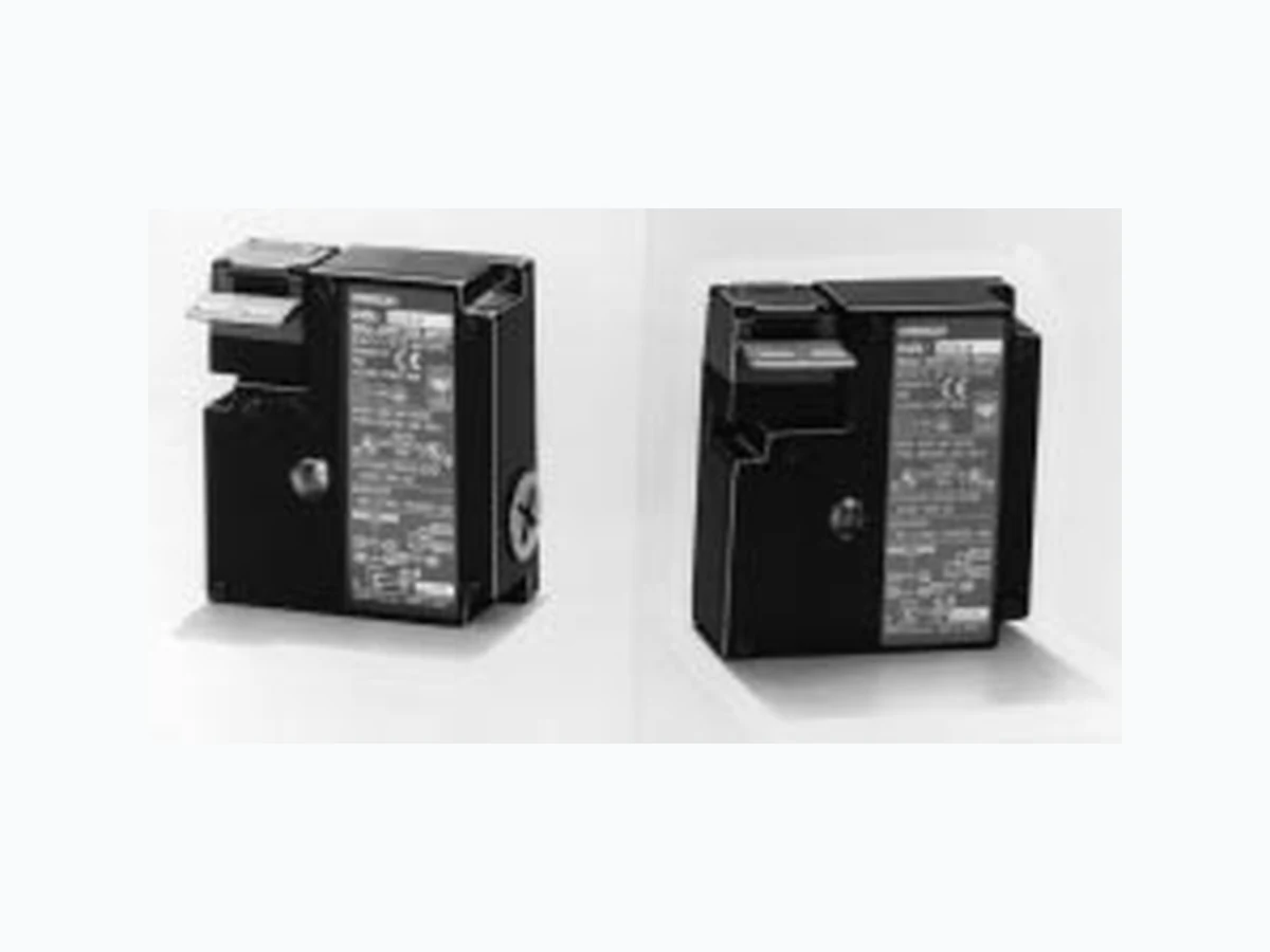
Compact Guard-locking Interlock Safety Door Switch D4DL Polymer housing, IP65, and slow-action contacts with positive opening → . 2 versions
- Mechanical lock/Solenoid release
- Solenoid lock/Mechanical release Rotatable operating head provides four possible key entry slots. Incorporates an indicator that shows operation status at a glance. Double-insulation structure requires no grounding terminals. (with mark) Three types of Operation Key are available:
- Horizontal mounting
- Vertical mounting
- Angle-adjustable vertical mounting Safety Standards Conformity: Machinery Directive, Low-voltage Directive, EN1088, SUVA Approval: Agency Standard File No. TÜV Rheinland EN60947-5-1 J9650736 BIA EN60947-5-1, GS-ET-19 9610568 UL (see note) UL508, CSA C22.2 No.14 E76675 SUVA SUVA Pending Note: Approval for CSA C22.2 No. 14 is authorized by cu mark. Ec
Ordering Information
- Conduit Size (2-conduit) 1: Pg13.5 2: G 1/2 2. Built-in Switch (with Safety Switch and Lock Monitor Switch Contacts) C: 1NC/1NO slow-action contacts plus 1NC slow-action contact D: 2NC slow-action contacts plus 1NC slow-action contact 3. Head Mounting Direction F: Front 4. Door Lock and Release A: Mechanical lock / 24-VDC solenoid release (see note) B: Mechanical lock / 110-VAC solenoid release C: Mechanical lock / 230-VAC solenoid release G: 24-VDC solenoid lock / mechanical release (see note) H: 110-V AC solenoid lock / mechanical release J: 230-V AC solenoid lock / mechanical release 5. Indicator B: 10 to 115 VAC/VDC (with orange LED indicator) E: 100 to 250 VAC (with orange neon lamp indicator)
- Key Type 1: Horizontal mounting 2: V ertical mounting 3: Horizontal-adjustable vertical mounting 5: V ertical/Horizontal-adjustable vertical mounting Switches Solenoid voltage/indicator Lock and release types Contact configuration (Slow-action) Approved force-separation NC contact Connector size Model Solenoid: 24 VDC O LED 10 t 1 15 VDC/VAC Mechanical lock S l id l 1NC/1NO+1NC PG13.5 D4DL-1CFA-B ∗So e o d C Orange LED: 10 to 115 VDC/VAC ec a ca oc Solenoid release C/ O C G1/2 D4DL-2CFA-B 2NC+1NC PG13.5 D4DL-1DFA-B ∗CC G1/2 D4DL-2DFA-B Solenoid lock Mhill 1NC/1NO+1NC PG13.5 D4DL-1CFG-B ∗So e o d oc Mechanical release C/ O C G1/2 D4DL-2CFG-B 2NC+1NC PG13.5 D4DL-1DFG-B ∗CC G1/2 D4DL-2DFG-B Solenoid: 110 VAC O LED 10 t 1 15 VDC/VAC Mechanical lock S l id l 1NC/1NO+1NC PG13.5 D4DL-1CFB-BSo e o d 0 C Orange LED: 10 to 115 VDC/VAC ec a ca oc Solenoid release C/ O C G1/2 D4DL-2CFB-B 2NC+1NC PG13.5 D4DL-1DFB-BCC G1/2 D4DL-2DFB-B Solenoid lock Mhill 1NC/1NO+1NC PG13.5 D4DL-1CFH-BSo e o d oc Mechanical release C/ O C G1/2 D4DL-2CFH-B 2NC+1NC PG13.5 D4DL-1DFH-BCC G1/2 D4DL-2DFH-B Solenoid: 230 VDC O l 100 t 250 V AC Mechanical lock S l id l 1NC/1NO+1NC PG13.5 D4DL-1CFC-ESo e o d 30 C Orange neon lamp: 100 to 250 VAC ec a ca oc Solenoid release C/ O C G1/2 D4DL-2CFC-E 2NC+1NC PG13.5 D4DL-1DFC-ECC G1/2 D4DL-2DFC-E Solenoid lock Mhill 1NC/1NO+1NC PG13.5 D4DL-1CFJ-ESo e o d oc Mechanical release C/ O C G1/2 D4DL-2CFJ-E 2NC+1NC PG13.5 D4DL-1DFJ-ECC G1/2 D4DL-2DFJ-E Note: Models marked with “∗” are recommended Operation Keys (Order Separately) Type Model Horizontal mounting D4DS-K1 Vertical mounting D4DS-K2 Horizontal-adjustable vertical mounting D4DS-K3 Vertical/Horizontal adjustable vertical mounting D4DS-K5
TÜV (EN60947-5-1) Item LED type Neon lamp type Utilization category AC-15 AC-15 Rated operating current (Ie) 6 A 3 A Rated operating voltage (Ue) 115 V 250 V Note: Use a 10-A fuse type gI or gG as a short-circuit protection device that conforms to IEC269. UL/CSA (UL508, CSA C22.2 No. 14) A300 Rated voltage Carry current Current (A) Voltagea ed o age Ca y cu e Make Break Make Break
120 VAC 10A 60 6 7,200 720
240 VAC
,0 0 0 Characteristics Degree of protection (see note 2) IP65 (EN60947-5-1) Life expectancy (see note 3) Mechanical:1,000,000 times min. Electrical:500,000 times min. Operating speed 0.05 to 0.5 m/s Operating frequency 30 operations/minute max. Rated frequency 50/60 Hz Positive opening force (see note 4) 58.84 N {6 kgf} min. (EN60947-5-1) Positive opening travel (see note 4) 10 mm min. (EN60947-5-1) Holding force 500 N {51 kgf} min. (GS-ET-19) Insulation resistance 100 MΩ min. (at 500 VDC) Rated insulation voltage (Ui) 300 V (EN60947-5-1) Conventional enclosed thermal current (Ithe)
10 A (EN60947-5-1)
Rated impulse voltage (Uimp) Between terminals of same or different polarity, each terminal and ground, and each terminal and non-current-carrying metal part: 4 kV Between the solenoid and non-current-carrying metal part: 0.8 kV for 24 VDC solenoid, 2.5 kV for 110 VAC solenoid, and 4 kV for 230 VAC solenoid (EN60947-5-1) Conditional short-circuit current 100 A (EN60947-5-1) Pollution degree (operating environment)3 (EN60947-5-1) Protection against electric shock Class II (double insulation) Switching overvoltage 1,500 V max. (EN60947-5-1) Contact resistance 25 mΩ max. (initial value) Vibration resistance Malfunction:10 to 55 Hz, 0.75-mm single amplitude Shock resistance Mechanical:1,000 m/s2 (100G) min. Malfunction:300 m/s2 (30G) min. Ambient temperature Operating: –10°C to 55°C with no icing Ambient humidity Operating: 95% max. Weight Approx. 340 g (D4DL-1CFA-B) Material Body and actuator flange Glass-fiber reinforced thermoplast, self-extinguishingae a Actuator Stainless steel Note: 1. The above values are initial values. 2. Although the switch box is protected from dust or water penetration, do not use the D4DL in places where foreign material may penetrate through the key hole on the head, otherwise switch damage or malfunctioning may occur. 3. The above mechanical or electrical life is ensured at an ambient temperature of 5°C to 35°C and an ambient humidity of 40% to 70%. 4. These values must be satisfied to ensure safe operation.
Item 24 VDC 110 VAC 230 VAC Rated operating voltage24 VDC +10% /–15% (100% ED) 110 VAC ±10% (100% ED) 230 VAC ±10% (100% ED) Current consumption Approx. 200 mA Approx. 50 mA Approx. 30 mA Insulation Class F (130°C max.) Class F (130°C max.) Class F (130°C max.) Indicator Item LED Neon lamp Rated voltage 10 to 115 VAC/VDC 100 to 250 VAC Current leakage Approx. 1 mA Approx. 1.9 mA Color Orange Orange Nomenclature Operation key hole Terminal E3 Terminal E4 Operation key hole Cam Terminal 11 Terminal 12 Terminal 23 Terminal 24 Main switch Indicator Release key Conduit opening Solenoid Lock monitor switch Terminal E1 ( ) Terminal E2 ( ) Conduit opening Terminal 32 Terminal 31
Operation PrinciplesMechanical lock model Guard Inside equipment Lock spring 23 24 31 32
- Door closed
- Access to machine is not allowed.
- Lock spring locks the door.
- Power to solenoid
- Door can be opened. Solenoid lock model Lock releasing spring 23 24 31 32
- Door opened
- Access to machine is allowed.
- Solenoid: OFF
- Lock releasing spring releases the door lock.
- Solenoid: OFF
- Door can be opened.
- Solenoid: ON
- Door locked
- Access to the machine is not allowed.
Indicates conditions where the Key is inserted and the lock is applied. Connect the terminals 12 to 31 to conform to BIA GS-ET-19. Model Contact Contact form Diagram Remarks D4DL-C - 1NC/1NO + 1NC Lock position ON Travel Key fully inserted. Key fully extracted. Only terminals 11, 12, 31, and 32 have an positive opening mechanism. The terminals 11/12 and 23/24 can be used as opposing poles. D4DL-D - 2NC + 1NC Lock position ON Travel Key fully inserted. Key fully extracted. Terminals 11, 12, 21, 22, 31, and 32 have a positive opening mechanism. The terminals 1 1/12 and 21/22 can be used as opposing poles. Indicator Internal Circuit Diagram LED Type (10 to 115 VAC/DC) Constant-current diode LED (orange) Neon Lamp Type (100 to 250 VAC) R=130 KΩ Neon lamp (orange) Circuit Connection Example Circuit is to be connected by user.
- Connect terminals 12 to 31. (To conform to BIA GS-ET-19.)
- Do not connect the indicator in parallel to the contacts. Doing so may allow short-circuit current to flow while the indicator is damaged, causing equipment malfunction.
- The 24-VDC solenoid has polarity. Be sure not to make wiring mistakes.
- In the following connection example, the indicator will be lit when the door is open. (D4DL-1CFA-B) Power supply side Solenoid Indicator Auxiliary circuit Safety circuit Ground (Orange)
Connection Example with OMRON G9S Safety Relay Unit G9S-321-T (24 VDC)+D4DL-CFA-/-CFB- /-CFC- (Mechanical Lock Type)+D4D-520N 3231 1211 23 24 1211 E/C0083SW T11 T12 T22 T21G9S D4DL D4DN PC G9S PC out put IN PC M S1: Safety Switch (D4D- 520N) S2: Safety Door Switch with solenoid lock (D4DL-CFA-B) S3: Pushbutton switch for solenoid E/C0083SW: Emergency-stop switch (A22E) KM1, KM2: Magnet Contactor (LC1-D) M: 3-phase motor Circuit Diagram Product Configuration PC output PC output (Stop signal) Feed back loop (Operation instruction) Emergency stop or standby Motor control system Operation instruction Motor control system (Reset signal) KM1 KM2 Closed Open Off delay timer OUT A22E Emergency stop PC output Contactor (off delay) Contactor (off delay) D4DL solenoid PBS c 12 C 12
G9S-301 (24 VDC)+D4DL-CFG- /-CFH- /-CFJ- (Solenoid Lock Type)+D4D-520 N 3231 1211 23 24 1211 E/C0083SW T11 T12 T22 T21G9S D4DL D4DN PC G9SPC output Circuit Diagram Product Configuration PC output PC output (Stop signal) Feed back loop (Operation instruction) Emergency stop or standby Reset switch Operation instruction Motor control system Closed Open KM1 KM2 S1: Safety Switch (D4D- 520N) S2: Safety Door Switch with solenoid lock (D4DL-CFG-B) S3: Reset switch E/C0083SW: Emergency-stop switch (A22E) KM1, KM2: Magnet Contactor (LC1-D) M: 3-phase motor A22E Emergency stop M Contactor Contactor
Note: All units are in millimeters unless otherwise indicated. Switch D4DL- - Four, head mounting screw Pre-travel distance Three, 4.3-dia. holes Indicator Three, cover counting screws Conduit cap Release key Conduit opening Operating characteristics Model Key insertion force 14.71 N {1,500 gf} max. Key extraction force 29.42 N {3,000 gf} max. Pre-travel distance 9 mm max. Movement before being locked 3 mm min. Operation Key D4DS-K1 Horizontal Mounting Four, R2.15 D4DS-K2 Vertical Mounting Four, R2.15 D4DS-K3 Horizontal-adjustable Vertical Mounting 9 dia. 4.5 dia.8 dia. Note: Each dimension has a tolerance of ±0.4 mm unless otherwise specified. D4DS-K5 Horizontal/Vertical-adjustable Vertical Mounting 18° Two, M4 9±0.1 41±0.1 43±0.1 Mounting Holes
D4DL + D4DS-K1 D4DL + D4DS-K2 D4DL + D4DS-K3 Key inserting position Key inserting position Key inserting position Horizontal insertion radius: R /C0121 200 Horizontal insertion radius: R /C0121 200 Horizontal insertion radius: R /C0121 50 Center tolerance of key hole: ±1 Center tolerance of key hole: ±1 Center tolerance of key hole: ±1 Key inserting position Key inserting position Key inserting position Vertical insertion radius: R /C0121 200 Vertical insertion radius: R /C0121 200 Vertical insertion radius: R /C0121 200 Center tolerance of key hole: ±1 Center tolerance of key hole: ±1 Center tolerance of key hole: ±1 45 min., 47.5 max. 45 min., 47.5 max. D4DL + D4DS-K5 51.9 min., 54.4 max. Center tolerance of key hole: ±1 mm. Horizontal insertion radius: R/C012150 Center tolerance of key hole: ±1 mm. Vertical insertion radius: R/C012150 Key inserting position 51.9 min., 54.4 max. Key inserting position Note: Each dimension has a tolerance of ±0.4 mm unless otherwise specified.
! WARNING Do not dismount the operation key from the door intentionally and insert it to the switch with the door open. Machine may start operating and injury or death may be caused. ! CAUTION Do not disassemble or touch inside under power-on. Electric shock hazard may be caused. Do not use metal connectors or conduits with this switch. Rigid connectors and conduits may damage the switch. The broken conduit hole may cause an electrical shock hazard. Install the operation key so that it will not hit the operator when the door is open. After-changing the release key to the UNLOCK position or inserting the operation key, change the head direction. Otherwise, the switch may malfunction and injuries may occur due to mis-operation of the device. NOTICE If the D4DL is applied to an emergency stop circuit or safety circuit for prevention of injury, use the NC contact, which incorporates a positive opening mechanism, and make sure that the D4DL oper- ates in positive mode. Furthermore, secure the D4DL with screws or equivalent parts that are tightened in a single direction so that the D4DL or operation key cannot be easily removed or provide a protection cover to the D4DL and post a warning label near the D4DL. To protect the D4DL from damage due to short-circuits, connect the D4DL in parallel to a fuse that has a breaking current 1.5 to 2 times the rated current of the D4DL. If the D4DL is used under EN-ap- proved rating conditions, use a 10 A fuse, type gI or gG conforming to IEC 269. Do not supply power to the D4DL while wiring the D4DL. In order to prevent the D4DL from burning due to overvoltage, inser- tion of a protection fuse into the solenoid circuits is recommended. Do not use the D4DL in locations subject to explosive or flammable gases. Make sure that the load current does not exceed the rated current and that the load terminals are wired correctly. Pay utmost attention to correctly wire each terminal. After mounting and adjusting the D4DL, make sure that the D4DL operates properly. If the D4DL is imposed with force exceeding the lock strength, the D4DL may break and the equipment may continue operating. Do not drop or disassemble the D4DL. Release Key The release key is used to unlock the D4DL in case of emergency or if the power supply to the D4DL fails. Use an appropriate tool to set the release key to UNLOCK so that the lock will be released and the door can be opened. The release key is set at the UNLOCK position. Set the release key to the LOCK position before use. Mechanical Lock Type Release key The release key applied to the door of a machine room ensures the safety of people adjusting the equipment in the machine room. If the release key is set to UNLOCK, the door will not be locked when the door is closed and no power will be supplied to the equipment. Do not use the release key to start or stop machines. To prevent the release key from being used carelessly by unautho- rized people, set the release key of the D4DL in normal operation to UNLOCK and seal the release key with seal wax. Mounting Be sure to mount the D4DL with a stopper as shown in the following illustration. Do not use the D4DL Switch as a stopper. Door Stopper Operation key Switch Set zone (0.5 to 3 mm) Solenoid Lock Type The solenoid lock locks the door only when power is supplied to the solenoid. Therefore, the door will be unlocked if the power supply to the solenoid fails. Therefore, do not use the solenoid lock type for machines that may be operating and dangerous even after the ma- chine stops operating because of inertia. Life Expectancy The life of the D4DL will vary with the switching conditions. Before applying the D4DL, test the D4DL under actual operating conditions and be sure to use the D4DL in actual operation within switching times that will not lower the performance of the D4DL. Operating Environment The D4DL is for indoor use only. Do not use the D4DL outdoors. Otherwise, the D4DL may malfunction. Do not use the D4DL in the following locations: Locations with severe changes in temperature Locations with excessive humidity that may cause condensation Locations with excessive vibration Locations where metal dust, oil, or chemical may be sprayed onto the D4DL Operation Key Be sure to use the dedicated Operation Key only. Do not operate the D4DL with anything other than the dedicated Operation Key. Otherwise, the safety of the system may not be maintained. Do not impose excessive force on the Operation Key inserted into the D4DL or drop the D4DL with the Operation Key inserted. Other- wise, the Operation Key may be deformed or broken. Force imposed Drop Secure the Operation Key with a one-way screw, or an equivalent, so that the Operation Key cannot be easily removed.
The D4DL may eventually break if the door opens accidentally due to the weight of the door, the vibration of the machine, or the bounc- ing of the door against the rubber bumper. Furthermore, the door may not unlocked if force is imposed on the operation key. Do not use the casing of the D4DL as a locking mechanism for the door in such cases and be sure to prepare a special lock within the lock range of the D4DL (i.e., 0.5 to 3 mm). Mounting Refer to page 10 for the mounting dimensions of the Operation Key. Be sure that the Operation Key can be inserted properly with a toler- ance of ±1 mm in the upward, downward, left, or right direction, otherwise the D4DL may be damaged. ±1 min. ±1 min. Tightening Torque Be sure to tighten each screw of the D4DL properly, otherwise the D4DL may malfunction. (3) (5) (1) (7) (6) (2) (4) Type Proper tightening torque (1) Terminal screw 0.59 to 0.78 N /C0083 m {6 to 8 kgf /C0083 cm/0.43 to 0.58 ft /C0083 lbf} (2) Cover mounting screw 0.78 to 0.88 N /C0083 m {8 to 9 kgf /C0083 cm/0.58 to 0.65 ft /C0083 lbf} (3) Head mounting screw 0.78 to 0.88 N /C0083 m {8 to 9 kgf /C0083 cm/0.58 to 0.65 ft /C0083 lbf} (4) Body mounting screw (M4) (see note) 0.49 to 0.69 N /C0083 m {5 to 7 kgf /C0083 cm/0.36 to 0.51 ft /C0083 lbf} (5) Operation Key mounting screw 2.35 to 2.75 N /C0083 m {24 to 28 kgf /C0083 cm/1.73 to 2.03 ft /C0083 lbf} (6) Connector at conduit opening 1.77 to 2.16 N /C0083 m {18 to 22 kgf /C0083 cm/1.30 to 1.59 ft /C0083 lbf} (7) Cap screw 1.27 to 1.67 N /C0083 m {13 to 17 kgf /C0083 cm/0.94 to 1.23 ft /C0083 lbf} Note: Tighten each screw together with a washer to the specified torque. Mounting Be sure the that D4DL operates properly after mounting and adjust- ing the D4DL. Use M4 screws (one-way screws, etc.) and washers to mount the D4DL and Operation Key securely.
Three, M4 Operation Key Mounting Holes
- Horizontal/Vertical Mounting D4DSK1/D4DS-K2 Two, M4
- Horizontal-adjustable Vertical Mounting D4DS-K3 Two, M4
- Horizontal/Vertical-adjustable Vertical Mounting D4DS-K5 Two, M4 9 ± 0.1 41±0.1 43±0.1 Head Direction By removing the four screws of the head, the mounting direction of the head can be changed. The head can be mounted in four direc- tions. Wiring Do not connect lead wires directly to the terminals. Be sure to con- nect the lead wires through insulation tubes and crimp terminals. The lead wires must be an AWB20 to AWG18 type (i.e., 0.5 to 10 mm 2 thick). D dia. dz dia. dz dia.: 3.7 D dia.: 4.5 B: 7.0 L: 20.2 F: 7.7 9.0 (mm) Wire the crimp terminal as shown in the following diagram so that it will not come in contact with the case or cover. Terminal screw Crimp terminal Correct Incorrect Conduit Opening Connect a recommended connector (see following table) to the opening of the conduit and tighten the connector to the proper torque. The casing may be damaged if an excessive tightening torque is applied. Be sure that the diameter of the cable connected to the connector is correct. Attach and tighten a conduit cap to the unused conduit opening when wiring the D4DL. The conduit cap is provided with the D4DL. Recommended Connectors Size Manufacturer Model Proper cable diameter G 1/2 OMRON SC-6 7.5 to 9.0 mmG /2 LAPP ST-PF1/2 5380-1002 6.0 to 12.0 mm Ohm Denki OA-W1609 7.0 to 9.0 mm Pg13.5 LAPP ST13.5 5301-5030 5.0 to 12.0 mm HEYCO 3216 4.3 to 11.9 mm Note: LAPP is a German manufacturer. Ohm Denki is a Japanese manufacturer. HEYCO is an American manufacturer. Maintenance and Repairs Please note in the machine manufacturer’s instruction manual that the user must not repair or maintain the switch and must contact the machine manufacturer for any repairs or maintenance. Others The solenoid radiates heat when power is supplied to the solenoid. Do not touch the solenoid while the power is supplied. Use the D4BL under conditions requiring greater rigidity, sealing performance, and oil resistance.
Industrial Control Components Division 28th Fl., Crystal Tower Bldg., 1-2-27, Shiromi, Chuo-ku, Osaka 540-6028 Japan Phone: (81)6-949-6025 Fax: (81)6-949-6029 ALL DIMENSIONS SHOWN ARE IN MILLIMETERS. To convert millimeters into inches, multiply by 0.03937. To convert grams into ounces, multiply by 0.03527. Cat. No. C107-E1-2 In the interest of product improvement, specifications are subject to change without notice. Printed in Japan 1198-1M (0497) a