
D2SW ETC
Document overview
- Manufacturer or author: Provided By www.digicamel.com(FREE DATASHEET DOWNLOAD SITE)
- PDF pages: 6
Technical content
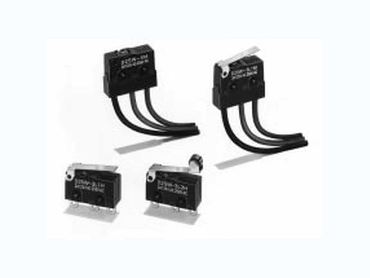
Watertight Miniature Basic Switch D2SW A High-quality Watertight Miniature Basic Switch Conforms to IP67 Monoblock construction assures high sealing capability and is ideal for dusty places or where water is sprayed. A wide operating temperature range of –40°C to 85°C is ideal for any operating environment. Ideal for the automobile, agricultural machinery, automatic vending machine, refrigerator, ice- manufacturing, bath equipment, hot-water supply, air conditioner, and factory machine industries, which require highly environment-resistive capabil- ities. RC D E V
Ordering Information
Actuator 3 A 0.1A Pin plunger Solder terminals D2SW-3H D2SW -01H (see note 2)pu g e Tab terminals (#110) D2SW-3T D2SW-01T PCB terminals D2SW-3D D2SW-01D With lead wires D2SW -3M (see note 3) D2SW -01M (see note 3) Hinge lever Solder terminals D2SW-3L1H D2SW -01L1H (see note 2)g eee Tab terminals (#110) D2SW-3L1T D2SW-01L1T PCB terminals D2SW-3L1D D2SW-01L1D With lead wires D2SW -3L1M (see note 3) D2SW -01L1M (see note 3) Simulated hinge lever Solder terminals D2SW-3L3H D2SW -01L3H (see note 2)S u a e d g eee Tab terminals (#110) D2SW-3L3T D2SW-01L3T PCB terminals D2SW-3L3D D2SW-01L3D With lead wires D2SW -3L3M (see note 3) D2SW -01L3M (see note 3) Hinge roller lever Solder terminals D2SW-3L2H D2SW -01L2H (see note 2)g eoe ee Tab terminals (#110) D2SW-3L2T D2SW-01L2T PCB terminals D2SW-3L2D D2SW-01L2D With lead wires D2SW -3L2M (see note 3) D2SW -01L2M (see note 3) Note: 1. The standard lengths of the lead wires (AV0.5f) of models incorporating them are 30 cm. 2. EN61058-1 (IEC1058-1) approved by VDE. 3. UL/CSA approved lead-wired models use UL/CSA approved lead wire. Model name changes from D2SW-M to D2SW-MS.
Non-inductive load Inductive laod Resistive load Lamp load Inductive load Motor load Model Rated voltage NC NO NC NO NC NO NC NO D2SW-3 125 VAC 3 A 1 A 0.5 A 1 A 0.5 A 1 A 0.5 A
30 VDC 3 A 1 A 1 A 1 A
Note: 1. The above current ratings are the values of the steady-state current. 3. Lamp load has an inrush current of 10 times the steady-state current. 4. Motor load has an inrush current of 6 times the steady-state current. Approved Standards UL (File No. E32667)/CSA (File No. LR21642) D2SW-3 : 3 A at 125 VAC, 2 A at 250 VAC D2SW-01 : 0.1 A at 125 VAC, 0.1 A at 30 VDC VDE (Licence No. 85002)/EN61058-1 (IEC1058-1) Approved D2SW-01 H: 0.1 A at 125 VAC Contact Item D2SW-3 D2SW-01 Specification Rivet Crossbar Material Silver Gold alloy Contact Form NC (Red*) NO (Blue*) COM (Black*) *Indicates the color of the lead wire.
(see note) 0.1 mm to 1 m/s (at pin plunger) Operating frequency Mechanical:300 operations/min Electrical:60 operations/min Insulation resistance 100 MΩ min. (at 500 VDC) Contact resistance 50 mΩ max. (initial value) for lead wire models70 mΩ max. (initial value) for lead wire models Dielectric strength 1,000 VAC, 50/60 Hz for 1 min between contacts of the same polarity 1,500 VAC, 50/60 Hz for 1 min between current-carrying metal parts and ground, and between each terminal and non-current-carrying metal part
600 VAC, 50/60 Hz for 1 min between contacts
1,500 VAC, 50/60 Hz for 1 min between current-carrying metal parts and ground, and between each terminal and non-current-carrying metal part Inrush current NO: 10 A NC: 20 A NO: 1 A NC: 1 A Vibration resistance Malfunction: 10 to 55 Hz, 1.5-mm double amplitude Shock resistance Malfunction: 300 m/s2 (approx. 30G) Life expectancy Mechanical:5,000,000 operations min. (OT value) Electrical:200,000 operations min. (3 A at 125 VAC), 100,000 operations min. (2 A at 250 VAC) Mechanical:5,000,000 operations min. (OT value) Electrical:200,000 operations min. Ambient temperature Operating: –40°C to 85°C (with no icing) Ambient humidity Operating: 95% max. Enclosure ratings IP67 for lead wire models IP50 for terminal models Weight Terminal model: 2 g, Lead wire model: 10 g Note: The operating speed value shown is for pin plunger models. For hinge lever models, this speed is for the plunger parts. VDE-approved Characteristics (EN61058-1) Degree of protection against electric shock Class 1 Ambient temperature 0°C to 85°C Operating cycles 50,000 Proof tracking index (PTI) 175 V Switch category (IEC335-1) A Operating Characteristics Type Pin plunger Hinge lever Simulated hinge lever Hinge roller lever D2SW-3 D2SW-01 D2SW-3L1 D2SW-01L1 D2SW-3L3 D2SW-01L3 D2SW-3L2 D2SW-01L2 PT max. 0.6 mm --- --- --- FP max. --- 13.6 mm 15.5 mm 19.3 mm
Note: 1. All units are in millimeters unless otherwise indicated. 2. Every actual model number includes the code instead of for the kind of terminals incorporated by the model. 3. Unless otherwise specified, a tolerance of ±0.4 mm applies to all dimensions. Terminal Model Note: The following illustrations and dimensions are for models with soldered terminals. Refer to Terminals for models with tab (#110) and PCB terminals. The dimensions not described are the same as those of models with pin plungers. Pin Plunger D2SW-3 D2SW-01 Hinge Lever D2SW-3L1 D2SW-01L1 Simulated Hinge Lever D2SW-3L3 D2SW-01L3 0.5 6.4±0.2 PT OP 2.9 7.710.1 R0.8 1.6 3.2 1.8 dia. 7.5±0.1 7.3 3.3±0.1 1.8 1.6 2.5 dia.±0.07 5.15 0.55 19.8±0.2 15.5±0.2 18.7±0.2 9.5±0.1 8.5±0.2 14.5 OP t = 0.3 Stainless steel lever 5.9 3.6 15.8 OP FP 5.9 3.6 t = 0.3 Stainless steel lever 2.35+0.1 –0.05 2.35+0.1 –0.05 dia. holes FP R1.3 Hinge Roller Lever D2SW-3L2 D2SW-01L2 t = 0.3 Stainless steel lever 14.5 OP FP 5.9 4.8 dia. x 3.2 Polyacetal roller
Note: The following illustration and dimensions are for models with pin plungers. The dimensions and operating characteristics of the actua- tors of models incorporating them are the same as those of the actuators of models with both actuators and terminals. Common terminal (black) Vinyl insulator Normally open terminal (blue) Stranded annealed copper wires Normally closed terminal (red) 2.9 9.2 7.5±0.1 1.8 dia. 16.4 16.9 300±10 (5) 6.4±0.221.25.15 9.5±0.1 2.35+0.1 –0.05 2.35+0.1 –0.05 dia. holes 2.5 dia.±0.07 0.7 Kind of Terminals 3.3±0.1 2.9 10.1 6.6 Three, 2.8 8.7±0.2 5.15 9.5±0.1 15.5±0.2 19.8±0.2 2.15 0.5 6.4±0.2 Three, 1.2 dia. holes 7.3 3.3±0.1 1.8 1.6 2.9 R0.8 1.6 3.2 6.4±0.2 0.5 19.8±0.2 8.5±0.2 5.15 9.5±0.1 15.5±0.2 18.7±0.2 7.2 3.3±0.1 0.8 1.2 8.8±0.2 5.15 1.85 9.5±0.1 Three, 1.35 dia. to 1.5 holes PCB thickness t = 1.6 mm 1.3 6.4±0.2 0.5 1.8±0.12.9 0.7 3.9 Solder Terminals Tab Terminals (#110) PCB Terminals PCB Mounting 8.8+0.15 –0.05 16.1±0.1 0.55 19.8±0.2 16.1±0.2
Use two M3 mounting screws with spring washers to mount the switch. Tighten the screws to a torque of 0.23 to 0.26 N /C0083 m (2.3 to 2.7 kgf /C0083 cm). Mounting Holes 9.5 Two 2.4 dia. or M2.3 mounting holes When soldering a lead wire to a terminal of the D2SW, use a solder- ing iron with a maximum capacity of 60 W and do not take more than 5 s to solder the lead wire, otherwise the characteristics of the D2SW may be altered. Make sure that there is no icing when using the D2SW at low ambi- ent temperatures. Operations Make sure that the switching object is perfectly separated from the actuator when the switch is not operated and the actuator is pressed appropriately by the switching object when the switch is operated. The switch should be set so that its stroke will be within the rated OT when the switch is operated. Install the switching object so that its moving direction is the same as that of the actuator. Handle D2SW models with pin plungers with care so that the sealing rubber parts around the pin plungers will not be damaged. Recommended conductor size for the 0.1 A-series solder terminal is AWG26 to 18 (0.13 to 0.83 mm2). Enclosure Ratings The D2SW was tested underwater and passed the following water- tightness tests, which however, does not mean that the D2SW can be used in the water. JIS C0920 (rules for testing the watertightness of electrical devices and materials), class 7 (watertightness test). Refer to the following illustration for the test method. IEC Publication 529, class IP67. Refer to the following illustration for the test method. Note: The object to be tested is left in the water for 30 minutes on condition that the distance between the surface of the water and the top of the object be 15 cm minimum and the distance between the surface of the water and the bottom of the object be 1 m minimum. ÉÉÉÉ ÉÉÉÉ ÉÉÉÉ ÉÉÉÉ Water Left for 30 mins. Tested object 1m min. 15cm min. ALL DIMENSIONS SHOWN ARE IN MILLIMETERS. To convert millimeters into inches, multiply by 0.03937. To convert grams into ounces, multiply by 0.03527. Cat. No. C97-E1-1