
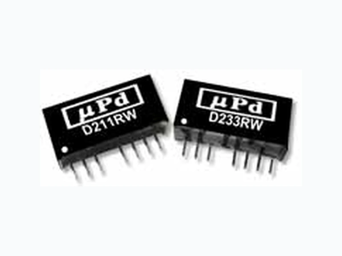
D221RW ETC1
Document overview
- Manufacturer or author: Provided By www.digicamel.com(FREE DATASHEET DOWNLOAD SITE)
- PDF pages: 2
Technical content
/square6 Miniature SIP Package /square6 2:1 Input Voltage Range /square6 2W Output Power /square6 Regulated Outputs /square6 Remote ON/OFF /square6 Low Cost Electrical Specifi cations Specifi cations typical @ +251C with nominal input voltage & rated output current, unless otherwise noted. Specifi cations subject to change without notice. MicroPower Direct Miniature SIP, 2W Wide Input Range DC/DC Converters D200RW Series MicroPower Direct /square6 TEL: (781) 344-8226 /square6 FAX: (781) 344-8481 /square6 E-Mail: sales@micropowerdirect.com /square6 WEB: www/micropowerdirect.com Input Parameter Conditions Min. Typ. Max. Units Input Start Voltage 5 VDC Input 3.5 4.0 4.5 VDC12 VDC Input 4.5 7.0 9.0 24 VDC Input 8.0 12.0 24.0 48 VDC Input 16.0 24.0 36.0 Input Filter Internal Capacitor Reverse Polarity Input Current 1.0 A Short Circuit Input Power 1,500 mW Output Parameter Conditions Min. Typ. Max. Units Output Voltage Accuracy ±1.0 ±2.0 % Line Regulation Vin = Min to Max ±0.3 ±0.5 % Load Regulation Iout = 25% to 100% ±0.5 ±0.75 % Ripple & Noise (20 MHz) (Note 1) 30 50 mV P - P Ripple & Noise (20 MHz) Over Line, Load & Temp. 75 mV P - P Ripple & Noise (20 MHz) 15 mV rms Output Power Protection 120 % Transient Response Time (Note 2) 50% Load Step Change 100 300 µSec Transient Response Deviation ±3.0 ±5.0 % Temperature Coeffi cient ±0.01 ±0.02 %/ °C Output Short Circuit Continuous General Parameter Conditions Min. Typ. Max. Units Isolation Voltage 60 Seconds 1,000 VDC Isolation Test Voltage Flash Tested For 1 Sec 1,100 VDC Isolation Resistance 1,000 VDC 1,000 M Ω Isolation Capacitance 100 kHz, 1V 65 120 pF Switching Frequency 100 300 650 kHz Environmental Parameter Conditions Min. Typ. Max. Units Operating Temperature Range Ambient -40 +25 +85 °C Operating Temperature Range Case -25 +25 +90 °C Storage Temperature Range -55 +105 °C Cooling Free Air Convection Humidity RH, Non-condensing 95 % Physical Case Material Non-Conductive Black Plastic Weight 0.17 Oz (4.8g) Reliability Specifi cations Parameter Conditions Min. Typ. Max. Units MTBF MIL HDBK 217F, 25 °C, Gnd Benign 1.0 MHours Absolute Maximum Ratings Parameter Conditions Min. Typ. Max. Units Input Voltage Surge (1 Sec) 5 VDC Input -0.7 15.0 VDC12 VDC Input -0.7 25.0 24 VDC Input -0.7 50.0 48 VDC Input -0.7 100.0 Lead Temperature 1.5 mm From Case For 10 Sec 260 °C Internal Power Dissipation All Models 3,500 mW Caution: Exceeding Absolute Maximum Ratings may damage the module. These are not continuous operating ratings.
232 Tosca Drive, Stoughton, MA 02072
www.micropowerdirect.com sales@micropowerdirect.com phone: (781) 344 - 8226 * fax: (781) 344 - 8481 MicroPower Direct Capacitive Load Model Selection Guide Derating Curve 100 -40 -20 0 15 30 50 60 70 80 85 90 95 100 Output Power % Ambient Temperature (°C)
100 LFM 200 LFM 400 LFMFree Air
0.37 (9.3) 0.86 (21.8) 3 5612 0.70 (17.8) 0.10 (2.5) 0.02 (0.5) 0.01 (0.25) 0.02 (0.5) 0.44 (11.1) 0.126 (3.2) 0.05 (1.25) Bottom View Side View 0.08 (2.0) Model Number Input Output Effi ciency (%, Typ) Fuse Rating Slow-Blow (mA) Voltage (VDC) Current (mA) Voltage (VDC) Current (mA, Max) Current (mA, Min)Nominal Range Full-Load No-Load Notes: 1. When measuring output ripple, it is recommended that an external 0.47 µF ceramic capacitor be placed from the +Vout pin to the -Vout pin. 2. Transient recovery is measured to within a 1% er- ror band for a load step change of 50 to 100%. 3. Operation at no-load will not damage these units. However, they may not meet all specifi cations. To maintain specifi ed operation, the minimum output loading given in the table above must be maintained. 4. It is recommended that a fuse be used on the input of a power supply for protection. See the table above for the correct rating. Pin Function 1- V i n 2+ V i n
3 Remote ON/OFF
5 No Function
8 No Function
Mechanical Notes:
- All dimensions are typical in inch es (mm)
- Tolerance x.xx = ±0.01 (±0.25)
- Pin 1 is marked by a “dot” or indentation on the side of the unit
- Leads are tin plated for improved solderability. Parameter Min Max Supply On Under 1 VDC or Open Circuit Supply Off 2.7 VDC Standby Input Current 0.2 mA Control Input Current (On) -0.4 mA Control Input Current (Off) 1 mA Control Common Referenced to -Vin (pin 1) Remote ON/OFF Models (Vout) 3.3V 5V 12V Units Max. Capacitive Load 2,200 1,000 170 µF