
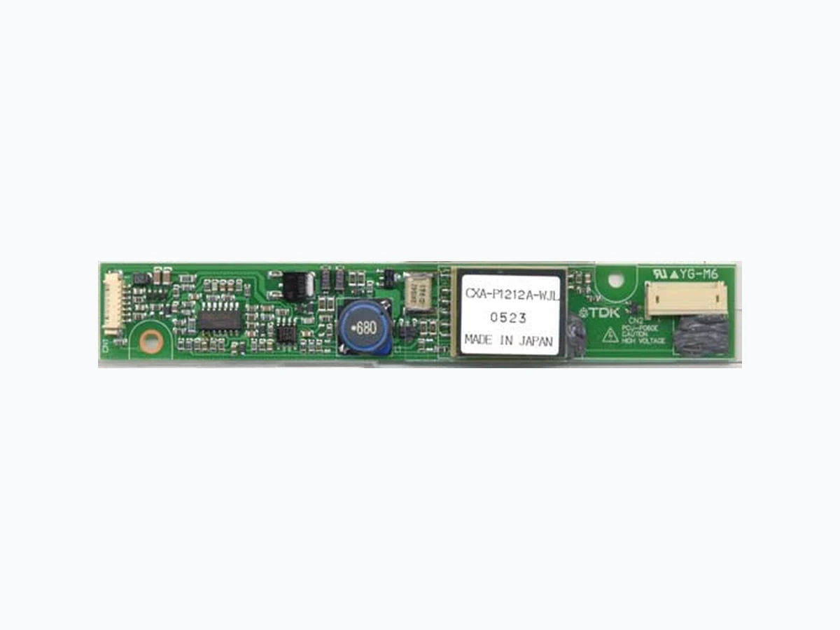
CXA-P1212A-WJL POWER-SYSTEMS
Document overview
- Manufacturer or author: Provided By www.digicamel.com(FREE DATASHEET DOWNLOAD SITE)
- PDF pages: 2
Technical content
CXA-P1212A-WJL (8W DOUBLE OUTPUTS WITH DIMMING FUNCTION) DC-AC INVERTER UNIT Power Systems – The Power Solution Web: www.Power-Systems.de Address: Dörnet 8 ; 74360 Ilsfeld-Auenstein / Germany Email: Info@Power-Systems.de Tel. : + 49 / 70 62 / 67 59 - 6 Fax: + 49 / 70 62 / 67 59 - 80 All specification are subject to change without notice. Page ( 1 / 2 ) VER, 08 March 2004 DESCRIPTION : This DC to AC Inverter was developed for many other low LCD Backlight power supply as low profile applications, either for LCD Monitor or Industrial PC. Applicable LCD; 10 to 15 inches double lamp type Lamp Voltage 600Vrms Lamp Current 6mArms Lamp Start Up Voltage 1700Vrms (Vin : 12V) FEATURES : PWM dimming type. Current Feedback Circuit High Efficiency Low noise with voltage resonant circuit Regulated output current TEMPERATURE & HUMDITY : Operating Temperature Range -10 ~ +70 Storage Temperature Range -30 ~ +85 Humidity 95 %RH max DIMENSIONS : °C°C °C°C ± 0.3 2Insulation sheet4 No. Part Description PWB Connector CN1 Connector CN2,3 Note UL94V-0 t=1.0mm 53261-0790 SM03(7-D1)B-BHS-1 or SM04(4.0)B-BHS-1 (JST) Qty. Item (Molex) Unit : mm Weight :25 (g) typ. Vhigh2 CN2 : SM03(7-D1)B-BHS-1or SM04(4.0)B-BHS-1 (JST) CN2-1 CN2-2 CN2-3 N.C. Pin Symbol Note Vhigh1 600Vrms (6mArms) Vlow (2V)CN2-4 600Vrms (6mArms) FR60 t=0.38mm (1.6) 10MAX (High Voltage generation area 75mm) CN1-1 CN1-7 (2) CN2 CN1 CXA-P1212A-WJL 9615 MADE IN JAPAN CN2-1 Silicone CN2-4 1 23 2 - Ø3.5 147 10712 CAUTION HIGH VOLTAGE 4 14 3.5 21.5 24.0 MAX. CN1-7 CN1-6 0 ~ 0.4V : OFF 2.5V ~ Vin : ON Pin CN1-1 CN1-2 CN1-3 CN1-4 CN1-5 Symbol Vin GND Vrmt Vbr2 / Rbr2 Vbr1 / Rbr1 Note 10.8 ~ 13.2V 0 V 0 -0.4V/2.5V-Vin (Active-High) 0 ~ 0.6V / 0 ~ 10k GND / 0 ~ 10k CN1 : 53261-0790 (Molex) Ω Ω ± 0.2 ± 0.3 ± 0.3 ± 0.5 ± 0.3 ± 0.3 ± 0.5
CXA-P1212A-WJL (8W DOUBLE OUTPUTS WITH DIMMING FUNCTION) DC-AC INVERTER UNIT Power Systems – The Power Solution Web: www.Power-Systems.de Address: Dörnet 8 ; 74360 Ilsfeld-Auenstein / Germany Email: Info@Power-Systems.de Tel. : + 49 / 70 62 / 67 59 - 6 Fax: + 49 / 70 62 / 67 59 - 80 All specification are subject to change without notice. Page ( 2 / 2 ) VER, 08 March 2004 TEST CIRCUIT : SW1 a b Operation of unit Operation Non operation SW2 a b Voltage dimming Variable resistance dimming Operation of unit Vbr=0~0.6V VR=0~10kΩ RL2 RL1 Io2 Io1 V 1000:1 PROBE VinIin Vo F CN1-1 CN1-2 CN1-3 CN1-4 CN1-5 CN1-6 CN1-7 CN2-1 CN2-4 F CN2-2 SW1a b 0/5V SW2a b 0 ~ 0.6V Rbr Q6 C10 C25 Vrmt Vbr 10.8 ~ 13.2V V A A V Ω10k ELECTRICAL CHARACTERISTICS : Output Current Input Current Frequency Open Voltage Parameters Symbol Conditions RL (k )Ta ( )Vin (V) NoteUnitSpecifications Iout Iin FL Vopen -10 ~ +70 5.5 6.0 6.5 1.2 Adc kHz Vrms typ.min. max.Vbr / Rbr 2.0 2.8 0.8 1.0 35 40 45 1500 - 1700 5.3 6.0 6.795 ~ 116 106 10.8 106 106 106 Ω mArms mArms mArms0V / 0 Ω 0V / 0Ω 0V / 0Ω 0V / 0Ω 0.6V / 10kΩ -10 ~ +70 -10 ~ +70 -10 ~ +70 0V / 0 Ω Max Brightness. Min Brightness. 12 ± 0.6 12 ± 0.6 12 ± 0.6 12 ± 0.6 12 ± 1.2 23 ± 5 Note :Please use minimum of 2mm clearance (all directions) between inverter high voltage area and any conductors. Please refer to mechanical drawing for marking of high voltage area. 23 ± 5