
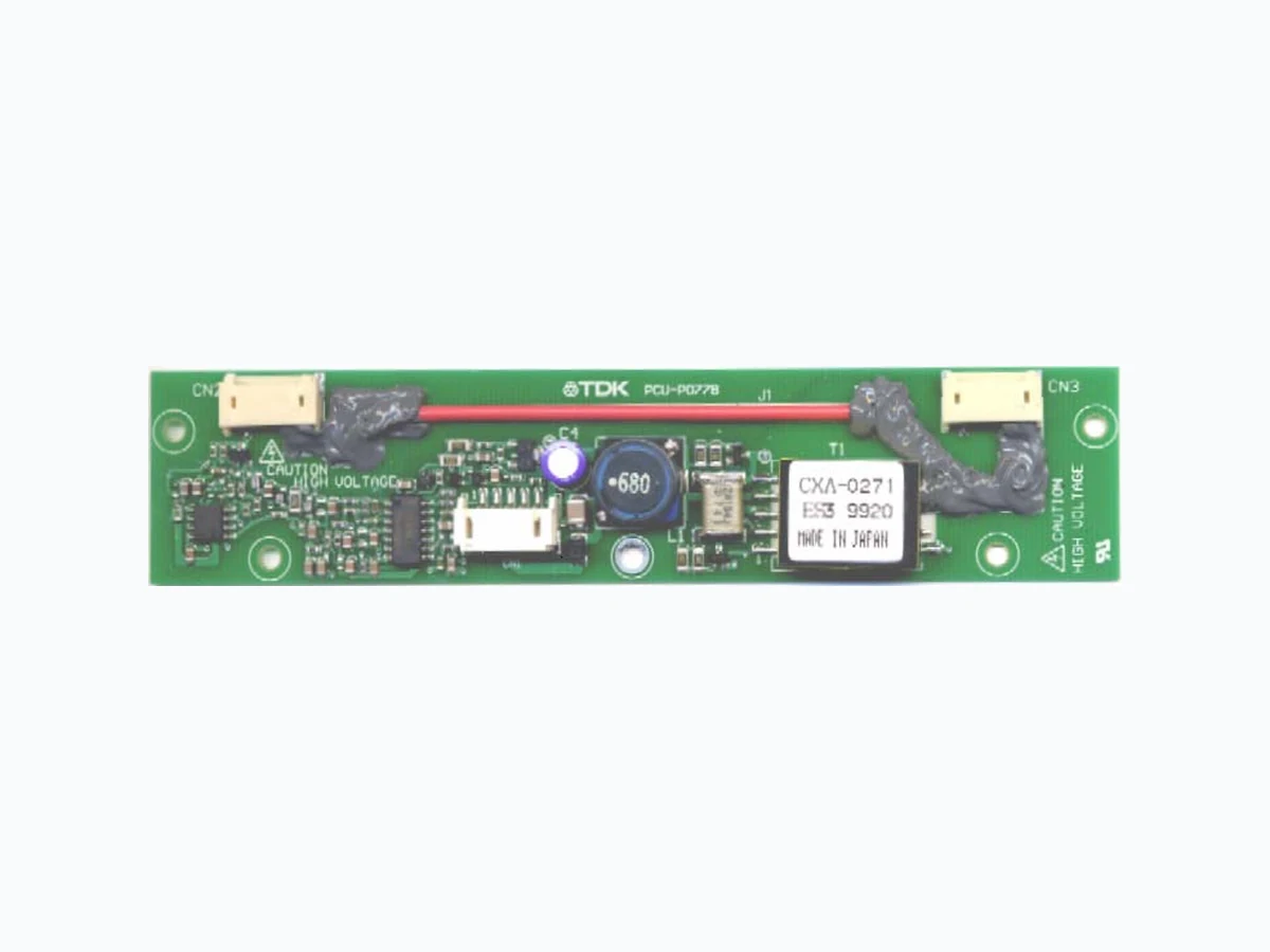
CXA-0271 POWER-SYSTEMS
Document overview
- Manufacturer or author: Provided By www.digicamel.com(FREE DATASHEET DOWNLOAD SITE)
- PDF pages: 4
Technical content
CXA-0271 (6W DOUBLE OUTPUT WITH DIMMING FUNCTION) DC-AC INVERTER UNIT (PRELIMINARY INFORMATION) Power Systems – The Power Solution Web: www.Power-Systems.de Address: Dörn et 8 ; 74360 Ilsfeld-Auenstein / Germany Emai: Info@Power-Systems.de Tel. : + 49 / 70 62 / 67 59 - 6 Fax: + 49 / 70 62 / 67 59 - 80 All specification are subject to change without notice. Page ( 1 / 4 ) VER, 01 October 2003 DESCRIPTION : This DC to AC Inverter was developed for many other low LCD Backlight power supply as low profile applications, either for LCD Monitor or Industrial PC. APPLICABLE LCD: 10 to 15 inches double lamp type Lamp Voltage 460V Lamp Current 6mA Lamp Start Up Voltage 1500Vrms (Vin : 12V) FEATURES : PWM dimming circuit Current Feedback Circuit High Efficiency Low noise with voltage resonant circuit Regulated output current TEMPERATURE & HUMDITY : Operating Temperature Range 0 °C ~ +60°C Storage Temperature Range -30 °C ~ +85°C Humidity 95 %RH max Unit : mm Weight : 21.0 (g) typ. 30 ± 0.5 3.5 ± 0.35 8MAX 18 ± 0.2 CN3 3 1 CXA-0271 Lot.9517 MADE IN JAPANCN1 CN2 CAUTION HIGH VOLTAGE (4) 5-ø3.0 ± 0.2 70 ± 0.5 8.5 ± 0.35 140 ± 0.5 (0.8) CAUTION HIGH VOLTAGE CXA-0271 Lot.9517 MADE IN JAPAN No. Part Discription Qty. Material Note
1 PCB 1 UL94V-0 (CEM-3) t=1mm
2 Connector CN1 1 S5B-PH-SM3 JST
3 Connector CN2 2 SM02(8.0)B-BHS-1 JST DIMENSIONS :
CXA-0271 (6W DOUBLE OUTPUT WITH DIMMING FUNCTION) DC-AC INVERTER UNIT (PRELIMINARY INFORMATION) Power Systems – The Power Solution Web: www.Power-Systems.de Address: Dörn et 8 ; 74360 Ilsfeld-Auenstein / Germany Emai: Info@Power-Systems.de Tel. : + 49 / 70 62 / 67 59 - 6 Fax: + 49 / 70 62 / 67 59 - 80 All specification are subject to change without notice. Page ( 2 / 4 ) VER, 01 October 2003 ELECTRICAL CHARACTERISTICS : Pin No. Symbols Ratings CN 1-1 Vin 10.8~13.2V CN 1-2 GND 0V CN 1-3 Vbr 0~2.5V CN 1-4 Vst 0/5V CN 1-5 Vrmt 0~13.2V: 0~0.4V OFF / 2~13.2V ON Pin No. Symbols Ratings CN 2-1 VHIGH1 460 Vrms CN 2-2 N.C. - CN 2-3 VLOW1 (5V) Pin No. Symbols Ratings CN 3-1 VHIGH2 460 Vrms CN 3-2 N.C. - CN 3-3 VLOW2 (5V) Input Side CN1: Output Side CN2: Output Side CN3: Vin (V) Vrmt (V) Vbr (V) Ta (°C) RL1 / RL2 (K Ω)M i n . T y p . M a x . 12±0.1 23±5 5.7 6 6.7 12±1.2 0~60 5 6 7 Iin1 5±0.25 - 550 700 Iin2 0~0.4 - - 1 F1 0 3 84 34 8 kHz F2 (Duty) 1.0±0.05 254 305 356 Hz Open Circuit Voltage Vopen 12±1.2 5±0.25 0 23±5 ∞ 1250 1500 - Vrms Dimming RL1=74, RL2= ∞ RL1=∞, RL2=74 RL1=∞, RL2=∞ RL1=74, RL2=74 - - 0 . 5 Warning 74±0.5 74±0.5Frequency 12±1.2 5±0.25 23±5 Input Current mA DC12±1.2 0~1.5 23±5 74±0.5 Unit Output Current Iout1/2 mArms Items Symbols Conditions Specification 5±0.25 0 0 1,25 2,5 Vbr (VDC) Iout (mArms) DIMMING CHARACTERISTICS (Reference):
CXA-0271 (6W DOUBLE OUTPUT WITH DIMMING FUNCTION) DC-AC INVERTER UNIT (PRELIMINARY INFORMATION) Power Systems – The Power Solution Web: www.Power-Systems.de Address: Dörn et 8 ; 74360 Ilsfeld-Auenstein / Germany Emai: Info@Power-Systems.de Tel. : + 49 / 70 62 / 67 59 - 6 Fax: + 49 / 70 62 / 67 59 - 80 All specification are subject to change without notice. Page ( 3 / 4 ) VER, 01 October 2003 Voltage Dimming Type APPLICATION (for example) A~ A~ RL2 RL1 Io2 Io1 V A V 1000:1 PROBE 0/5V Vin 10.8~13.2V Vrmt Vin Iin Vopen V Vbr0~ 2.5V F CN1-1 CN1-2 CN1-3 CN1-4 CN1-5 CN2-1 CN2-3 CN3-1 CN3-3 C10 V Vst TEST CIRCUIT: RL2 RL1 Iout Vopen 0/5V 10.8~ 13.2V Vrmt Vin Iin Vbr 2.5V 1000:1 CN1-1 (Vin)A- A F CN2-1 (VHIGH1) CN3-1 (VHIGH2)CN1-2 (GND) CN1-3 (Vbr) CN1-4 (Vst) CN1-5 (Vrmt) A Vst Vin V Iout CN3-3 (VLOW2) CN2-3 (VLOW1)S W b a
CXA-0271 (6W DOUBLE OUTPUT WITH DIMMING FUNCTION) DC-AC INVERTER UNIT (PRELIMINARY INFORMATION) Power Systems – The Power Solution Web: www.Power-Systems.de Address: Dörn et 8 ; 74360 Ilsfeld-Auenstein / Germany Emai: Info@Power-Systems.de Tel. : + 49 / 70 62 / 67 59 - 6 Fax: + 49 / 70 62 / 67 59 - 80 All specification are subject to change without notice. Page ( 4 / 4 ) VER, 01 October 2003 Note 1. For circuit connection, please prefer to test circuit diagram. Note 2. Please use minimum of 2mm clearance (all directions) between inverter high voltage area and any conductors. Please refer to mechanical drawing for marking of high voltage area. Note 3. Open voltage (strike voltage) is measured across the transformer secondary winding at no load as the reading at the output connector would be less than the actual value. Note 4. If the start voltage falls below Cold Cathode Tube strike voltage, the CCFL will not light up easily specially at lower ambient temperature. Please review mounting instruction to avoid any abnormal operation due to coupling/leakage capacitance of inverter high voltage area to any surrounding conductor. Note 5. Please check your lamp characteristic for minimum operational current and set the limit point in your design to avoid flickering and/or abnormal operation. Note 6. For proper operation of circuit protection (FUSE or IC PROTECTOR), please use minimum of 2A capacity for input power supply. Note 7. The warning signal: 5V in abnormal circumstances. Note 8. The brightness of the lamp changes at the change and this level, too, when the direction cjanges the input voltage lower than 12V of the standard. Note 10. In test circuit, if one of the switches CN2 or CN3 opens, then the warning signal will be activated (+5V).