Download PDF
CX74063-26 SKYWORKS
Document overview
- PDF pages: 59
Technical content
Page 1
DATA SHEET
CX74063-26: RF Transceiver for Multi-Band GSM, GPRS, and
EDGE Applications with Power Ramping Controller and
Integrated Crystal Oscillator with 26 MHz Output
APPLICATIONS
- GSM850, EGSM900, DCS1800, and PCS1900 handsets
- GPRS handsets and modules
- EDGE downlink support
FEATURES
- Direct down-conversion receiver eliminates the external image reject/IF filters
- Three separate LNAs with single-ended inputs
- RF gain range: GSM = 20 dB, DCS = 22 dB, PCS = 20 dB. Baseband gain range = 100 dB
- Gain selectable in 2 dB steps
- Integrated receive baseband filters with tunable bandwidth
- Integrated DC offset correction sequencer
- Reduced filtering requirements with translational loop transmit architecture
- Integrated transmit VCOs
- Wide RF range for quad band operation
- Integrated PAC loop
- Single integrated, fully programmable fractional-N synthesizer suitable for multi-slot GPRS operation
- Fully integrated wideband Ultra High Frequency (UHF) VCO
- Integrated crystal oscillator
- Separate enable lines for power management transmit, receive, and synthesizer modes
- Supply voltage down to 2.6 V
- Band select and front-end enable states may be exercised on output pins to control external circuitry
- Low external component count
- Optional bypass of baseband filtering for use with high dynamic range Analog to Digital Converters (ADCs) for current savings
- Interfaces to low dynamic range ADC
- Meets AM suppression requirements without baseband interaction
- 56-pin RFLGA 8x8 mm package
- Low power standby mode
DESCRIPTION The CX74063-26 transceiver is a highly integrated device for multi-band Global System for Mobile Communications™ (GSM™) or General Packet Radio Service (GPRS) applications. The device requires a minimal number of external components to complete a GSM radio subsystem. The CX74063-26 supports GSM850, EGSM900, DCS1800, and PCS1900 applications. The receiver also supports downlink Enhanced Data-Rate GSM Evolution (EDGE). The receive path implements a direct down-conversion architecture that eliminates the need for Intermediate Frequency (IF) components. The CX74063-26 receiver consists of three integrated Low Noise Amplifiers (LNAs), a quadrature demodulator, tunable receiver baseband filters, and a
DC-offset correction sequencer. In the transmit path, the device consists of an In-phase and Quadrature (I/Q) modulator within a frequency translation loop designed to perform frequency up-conversion with high output spectral purity. This loop also contains a phase-frequency detector, charge pump, mixer, programmable dividers, and high power transmit Voltage Controlled Oscillators (VCOs) with no external tank required. With the integrated gain controller (and an integrator ), the device realizes the Power Amplifier Control (PAC) functionality when combined with a coupler, a Radio Frequency (RF) detector and a Power Amplifier (PA). The CX74063-26 also features an integrated, fully
programmable, sigma-delta fractional-N synthesizer suitable for GPRS multi-slot operation. Except for the loop filter, the frequency synthesizer function, including a wideband VCO, is completely on-chip. The reference frequency for the synthesizer is supplied by the integrated crystal oscillator circuitry. The 56-pin 8x8 RF Land Grid Array (RFLGA™) device package and pin configuration are shown in Figure 1. A functional block diagram is shown in Figure 2. Signal pin assignments, functional pin descriptions, and equivalent circuitry are provided in Table 1.
Page 2
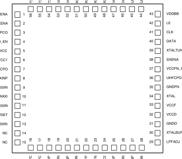
RXENA
TXENA
VCXO_EN
PDETVCC
TXCPO
LNA900IN
GNDLNA900
LNA1800IN
LNA1900IN
C1328
Figure 1. CX74063-26 Pinout – 56-Pin RFLGA (8 x 8 mm) (Top View)
Page 3
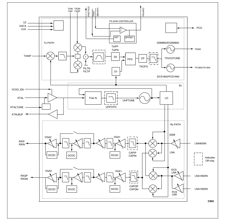
Figure 2. CX74063-26 Transceiver Block Diagram
Page 4
Table 1. CX74063-26 Signal Descriptions (1 of 5)
Pin #
Name
Description
Equivalent Circuit
| 1 | RXENA | Receiver enable input | |
| 2 | TXENA | Transmitter enable input | |
| 3 | PCO | Bi-directional band select | |
| 4 | VCXO_EN | VCXO enable pin | |
| 5 | PDETVCC | Bias for the RF Detector | Vout Vref |
| 6 | VCC1 | LNA and TX charge pump supply | VCC1 |
| 7 | TXCPO | Translational loop charge pump output | |
| 8 | TXINP | Translational loop feedback input | |
| 9 | LNA900IN | Low band LNA input for GSM850, EGSM900 | |
| 10 | GNDLNA900 | Low band LNA emitter ground |
Page 5
Table 1. CX74063-26 Signal Descriptions (2 of 5)
Pin #
Name
Description
Equivalent Circuit
| 11 | LNA1800IN | DCS LNA input | |
| 12 | PDET | Feedback Input to power control loop | |
| 13 | LNA1900IN | PCS LNA input | |
| 14 | NC | No connect | No connect |
| 15 | NC | No connect | No connect |
| 16 | PAVAPC | PA control output | Vout |
| 17 | BBVAPC | PA control Baseband input | |
| 18 | TXIP | TX I baseband input positive | |
| 19 | TXIN | TX I baseband input negative | |
| 20 | TXQP | TX Q baseband input positive | |
| 21 | TXQN | TX Q baseband input negative | |
| 22 | TXFP | TX IF filter output positive | |
| 23 | TXFN | TX IF filter output negative |
Page 6
Table 1. CX74063-26 Signal Descriptions (3 of 5)
Pin #
Name
Description
Equivalent Circuit
| 24 | VCC2 | RX mixer and TX loop supply | VCC2 |
| 25 | CAPIP | Capacitor filter I positive | |
| 26 | CAPIN | Capacitor filter I negative | |
| 27 | CAPQP | Capacitor filter Q positive | |
| 28 | CAPQN | Capacitor filter Q negative | |
| 29 | LPFADJ | LPF frequency setting resistor | |
| 30 | XTALBUF | Crystal oscillator buffer output | |
| 31 | GNDD | Synthesizer digital ground | |
| 32 | VCCD | Synthesizer digital supply | VCCD |
| 33 | VCCF | Synthesizer analog supply and crystal oscillator supply | VCCF |
| 34 | XTAL | Crystal input | |
| 35 | GNDFN | Synthesizer analog ground |
Page 7
Table 1. CX74063-26 Signal Descriptions (4 of 5)
Pin #
Name
Description
Equivalent Circuit
| 36 | UHFCPO | Synthesizer charge pump output | |
| 37 | VCCFN_CP | Synthesizer charge pump supply | VCCFN_CP |
| 38 | SXENA | Synthesizer enable input | |
| 39 | XTALTUNE | Crystal oscillator varactor control | |
| 40 | DATA | Serial bus data input | |
| 41 | CLK | Serial bus clock input | |
| 42 | LE | Serial bus latch enable input | |
| 43 | VDDBB | Digital CMOS supply | VDDBB |
| 44 | UHFBYP | Bypass capacitor for UHF VCO | |
| 45 | UHFTUNE | UHF VCO control input | |
| 46 | VCCUHF | UHF VCO supply | VCCUHF |
| 47 | VCC3 | LO chain supply | VCC3 |
Page 8
Table 1. CX74063-26 Signal Descriptions (5 of 5)
Pin #
Name
Description
Equivalent Circuit
| 48 | RXQN | Receiver output Q negative | |
| 49 | RXQP | Receiver output Q positive | |
| 50 | RXIN | Receiver output I negative | |
| 51 | RXIP | Receiver output I positive | |
| 52 | VCC4 | Baseband supply | VCC4 |
| 53 | VCCTXVCO | Transmit VCO supply | VCCTXVCO |
| 54 | TX900 | Low band transmit VCO | |
| 55 | TX1800/TX1900 | DCS and PCS transmit VCO output | |
| 56 | TXVCOTUNE | Transmit VCO control input |
Technical Description
The CX74063-26 transceiver contains the following sections, as shown in Figure 2.
- Receive section. Includes three integrated LNAs, a quadrature demodulator section that performs direct down conversion, baseband amplifier circuitry with I/Q outputs, and three stages of DC offset correction. The receiver can be calibrated to optimize IP2 performance.
- Synthesizer section. Includes an integrated on-chip VCO locked by a fractional-N synthesizer loop, and a crystal oscillator to supply the reference frequency.
- Transmit section. The TX path is a translational loop architecture consisting of an I/Q modulator, integrated high power VCOs, offset mixer, programmable divider, PFD, and charge pump. The device also provides integrated gain controller for the PAC loop, plus the bias generator for an external diode detector.
A 3-wire serial interface controls the transceiver and synthesizer. The receiver gain control, as well as the division ratios and charge pump currents in the synthesizer and transmitter, can be programmed using 24-bit words. These 24-bit words are programmed using the 3-wire input signals CLK, DATA, and LE. Pin 43 (VDDBB) is provided for the digital sections to allow power supply operation compatible with modern digital baseband devices. VDDBB is also used to supply registers 0 through 5 to maintain programmed values. The TXENA, RXENA, and SXENA signals separately enable the CX74063-26 transmitter, receiver, and synthesizer sections. TXENA and RXENA should be held low during programming.
SXENA should be held high during the programming of register 3 (IP2 calibration). (These timing signals are detailed in Figures 9, 10, and 11.)
Page 9
Receive Section LNA and Quadrature Demodulator Three separate LNAs are integrated to address different bands of operation. These LNAs have separate single-ended inputs, which are externally matched to 50 Ω. The gain is switchable between high (i.e., 15 dB typical) and low (i.e., –5 dB GSM, –7 dB DCS, and –5 dB PCS typical) settings. The LNA outputs feed into a quadrature demodulator that downconverts the RF signals directly to baseband. Two external 470 pF capacitors are required at the demodulator output to suppress the out-of- band blockers. Baseband Section An off-chip capacitor and three fixed poles of on-chip, low pass filtering provide rejection of strong in- and out-of-band
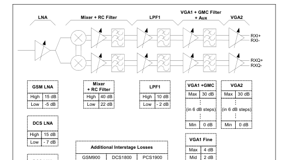
interferers. In addition, a tunable, four-pole gmC filter provides rejection of the adjacent channel blockers. Incorporated within the fixed-pole filters are two switchable gain stages of 18 dB and 12 dB gain steps, respectively. There is an additional programmable gain amplifier with a gain range from 0 to + 34 dB, selectable in 2 dB steps in the four-pole tunable filter. The final filter output feeds an amplifier with a gain range from 0 to 30 dB, selectable in 6 dB steps. There is an additional gain stage on the four-pole tunable filter output, the auxiliary gain stage, selectable at 0 dB or + 6 dB. The gain control ranges are shown in Figure 3. Recommended combinations of individual block gain settings
are shown in Table 22 for GSM900, Table 23 for DCS1800, and Table 24 for PCS1900. For added baseband interface flexibility, the four-pole filter, its associated Variable Gain Amplifier (VGA), and DC offset correction loop can be bypassed and turned off for current savings. In Table 2 the typical locations of all eight receiver baseband poles are given. The final four poles are produced by the tunable gmC filter, as set by the external resistor (recommended value is 39.2 kΩ, 1%) placed from pin 29 to ground. For these tunable poles, Table 2 gives the pole location as a function of this resistor.
DC Offset Correction Three DC offset correction (DCOC) loops ensure that DC offsets, generated in the CX74063-26, do not overload the baseband chain at any point. After compensation, the correction voltages are held on capacitors for the duration of the receive slot(s). Internally, on-chip timing is provided to generate the track and hold (T_H) signals for the three correction loops.
The timing diagram for the DC offset correction sequence with reference to the receive slot is shown in Figure 4. A rising edge on either the RXENA signal, selected via the serial interface, places the DC compensation circuitry in the track mode. The timing parameters for each of the three compensation loops, tt_H1, tt_H2, and tt_H3, and the time between compensation start and the LNA being turned on, tFEENA, are defined via an internal state machine. The state machine is preprogrammed with fixed default values, but may be readjusted via the serial interface. The timing parameters for the three compensation loops and the LNA power-up are each independently defined, relative to
the compensation start. Therefore, they may be programmed to occur in any order, but the sequences shown in Figure 4 and Figure 5 are recommended. The device default timing is shown in Figure 5, with a total time of 60 μs. Individual default timings are given in Table 17. For user-programmed timing, the total time may be set as short as approximately 10 μs when FREF has a 13 MHz clock applied. However, the shortest recommended total time is approximately 30 μs, since at the highest gain settings, the resulting DC may degrade as correction time is reduced. AM Suppression and IP2 Calibration For direct conversion GSM applications, it is imperative to have extremely low second-order distortion. Mathematically,
second-order distortion of a constant tone generates a DC- term proportional to the square of the amplitude. A strong interfering amplitude-modulated (AM) signal is therefore demodulated by second-order distortion in the receiver front end, and generates an interfering baseband signal.
Table 2. Receive Pole Locations
Stage
Typical Pole Location (rad/sec)
Pole Type
| Mixer + RC Filter | –1.0 x 10⁶ | Real (capacitors at pins 25-26 and 27-28 fixed at 470 pF) |
| –1.65 x 10⁶ | Real | |
| LPF1 | (–0.91 x 10⁶) ± j(1.35 x 10⁶) | Conjugate |
| VGA1 + gmC filter | (–0.91 x 106) x (39.2 kΩ/R) | Real (adjust with resistor at pin 29) |
| (–0.91 x 106) x (39.2 kΩ/R) | Real (adjust with resistor at pin 29) | |
| [(–0.46 x 10⁶) ± j(1.0 x 10⁶)] x (39.2 kΩ/R) | Conjugate (adjust with resistor at pin 29) |
Page 10
| GSM900 | DCS1800 | PCS1900 |
| 4.2 dB | 5.0 dB | 6.2 dB |
PCS LNA
Min 0 dB

Figure 3. Gain Control Settings
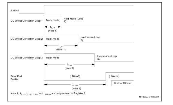
Figure 4. DC Offset Correction Timing (LNA Off During All of the DC Offset Correction Sequence)
Page 11
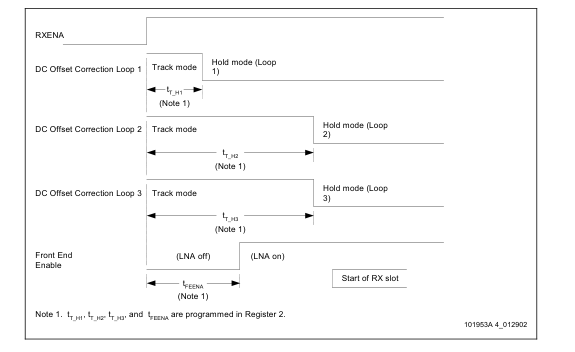
Figure 5. DC Offset Correction Timing (LNA On During Part of the DC Offset Correction Sequence)
A commonly used measure for receiver second-order distortion is the second-order intercept point, IP2. For example, to ensure that the unwanted baseband signals are 9 dB below the wanted signal required under the AM suppression test for type approval (see 3GPP TS 51.010-1), an input IP2 of 43 dBm is required: The CX74063-26 receiver includes a circuit that minimizes second-order distortion. This IP2 calibration circuit effectively compensates any second-order distortion in the receive chain that would otherwise generate unwanted baseband signals in the presence of strong interfering signals. When calibrated correctly, the CX74063-26 IP2 meets the GSM AM suppression
test requirements in all bands with good margin. To calibrate IP2, apply a strong RF signal at the receiver input and observe the resulting DC voltage level change at the receiver I/Q outputs. The exact frequency and level of the signal applied for the purpose of the calibration are not critical. The signal should, however, be within the receive band, but at least 6 MHz offset from the frequency to which the receiver is tuned. The level should be high enough tocause a notable DC shift at the I/Q outputs. A recommended value is –30 dBm at the LNA input, which applies to all three LNAs. A set of I/Q compensation coefficients can then be programmed to the device to minimize the DC voltage shift
resulting from the second-order distortion. When the DC due to the interfering signal is minimized, the IP2 performance is optimized.
Note: SXENA, pin 38, must be held high, and a clock signal must be present on XTAL, pin 34, during the programming of the IP2 calibration coefficients in register 3, see Table 18.
The IP2 calibration is a one-time factory calibration that should be done for each band and each individual device for optimum performance. The determined coefficients must be stored in nonvolatile memory and programmed to the CX74063-26 upon each power-up as part of device initialization. There are on- chip registers that must be programmed through register 3 with the appropriate IP2 coefficients for the band in use. As long as a supply voltage is maintained on pin 43, VDDBB, the IP2 coefficients for ILowband, IHighband, QLowband, QHighband, programmed to the device remain in the registers. After the supply voltage has been removed from VDDBB, the coefficients
must be re-programmed to the device again. Synthesizer Section The CX74063-26 includes a fully integrated UHF VCO with an on-chip LC tank. A single sigma-delta fractional-N synthesizer can phase-lock the local oscillator used in both transmit and receive paths to a precision frequency reference input. Fractional-N operation offers low phase noise and fast settling times, allowing for multiple slot applications such as GPRS. The CX74063-26 frequency stepping function with a 3 Hz resolution allows triple band operation in both transmit and receive bands using a fully integrated single integrated on-chip UHF VCO. The fine synthesizer resolution allows direct compensation or
adjustment for reference frequency errors. The fractional-N synthesizer consists of the following:
- VCO
- High frequency prescaler
- N-divider with a sigma-delta modulator
- Reference buffer and divider
- Fast phase frequency detector and charge pump
Page 12
The user must provide the following three parameters:
- The reference divider value, from 1 to 15
- The N-divider value, in a manner similar to an integer-N synthesizer
- A fractional ratio The generated frequency is given by the following equation:
FN + + N 5.3
f ref 22
2
f = VCO
R
where: fVCO = Generated VCO frequency N = N-divider ratio integer part FN = Fractional setting R = R-divider ratio fREF = Reference frequency UHF VCO Frequency Setting For the receiver, to tune the receive frequency, fRX, set the VCO frequency, fVCO, as follows:
3
- VCO
= f for GSM850/900 f RX 2 3
- VCO
= f for DCS1800 and PCS1900 f RX 4
For the transmitter VCO frequency, refer to the equations shown in Figure 6. Digital Frequency Centering The CX74063-26 uses a novel technique whereby the UHF VCO frequency range is re-centered each time the synthesizer is programmed. This technique is called Digital Frequency Centering (DFC). The DFC technique:
- Extends the VCO frequency coverage
- Speeds up settling time
- Ensures robust performance since the VCO is always operated at the center of its tuning range.
Each time the synthesizer is programmed, the DFC circuit is activated, and the VCO is centered to the programmed frequency in less than 20 µs. After this, normal Phase Locked Loop (PLL) operation is resumed and the fine settling of the frequency is finalized. The DFC typically adjusts the VCO center frequency to within a few MHz and no more than 5 MHz offset, and presets the tuning voltage to the center of the range before the PLL takes over. This speeds up frequency settling and ensures that the PLL control voltage never operates close to the rails.
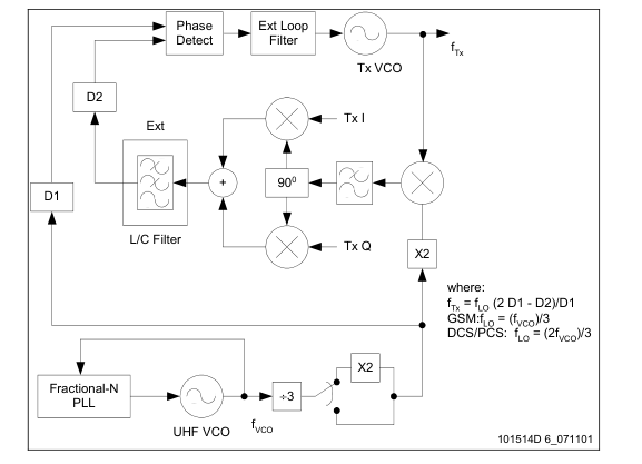
Figure 6. Transmitter Frequency Generation
Page 13
The DFC is an adaptive circuit that corrects for any VCO center frequency errors caused by variations of the integrated VCO circuit, temperature, supply voltage, aging etc. The VCO can be centered at any frequency in the range from 1.2 GHz to 1.55 GHz. Once centered, the VCO has a minimum analog tuning range of 30 MHz. No calibration or data storage is needed for DFC operation. It is activated by one of two events:
- When the synthesizer is programmed, the rising edge of the LE signal starts the DFC cycle and,
- When changing the level of the SXENA signal from low to high, thereby turning on the synthesizer, the rising edge of the SXENA signal starts the DFC cycle.
Crystal Oscillator A crystal oscillator is designed to provide the reference frequency for the synthesizer. As shown in Figure 7, the oscillator uses an external crystal to generate an accurate oscillation frequency. The reference frequency can be changed through coarse tuning with an integrated capacitor array or fine tuning with the integrated varactor diode. The coarse tuning is done by switching in and out (using a digital word programmed via the serial interface) the capacitor network (CAP_A and CAP_B) located at the input of the integrated buffer. The fine tuning is done by providing a tuning voltage to the integrated varactor diode. Table 20 describes the control bits.
An output buffer is provided to drive the baseband circuitry (XTALBUF, pin 30). The VCXO and buffer circuitry are powered from pin 33 (VCCF). When VCCF is ramped to a voltage greater than 2.6 V, the output buffer powers on. The oscillator core powers up when pin 4 (VCXO_EN) is set to logic 1. If pin 4 is tied permanently to logic 1, the R6 VCXO Control Register is set to a defined state by a power-on reset. Pin 4 should be held low if an external reference oscillator is used. The buffer may be disabled by programming bit 3 in the SX1 Control Register (see Table 13) to logic 0. Transmit Section To minimize the post-PA filtering requirements and any additional post-PA losses, the transmit path consists of a
vector modulator within a frequency translation loop. The translation loop consists of the following:
- Phase Frequency Detector (PFD) and charge pump
- Mixer with an operating range of 800 MHz to 2 GHz
- An in-loop modulator
- Two programmable dividers
- Two transmit VCOs Translational Loop The translational loop takes baseband analog I/Q signals and modulates them with the mixed product of transmitter output and LO signal, as shown in Figure 6. The unmodulated result is compared with a divided down LO at the PFD and the difference is used to control the transmit VCO. The on-chip Low Pass Filter (LPF) following the mixer attenuates the unwanted sidebands as well as harmonics.
Transmit VCOs Two on-chip transmit VCOs are designed to meet GSM850, EGSM900, DCS1800, and PCS1900 requirements. The transmit VCOs use the same DFC technique as described in the Synthesizer section to lock the translational loop. The rising edge on TXENA initializes the transmit DFC. Power Amplifier Gain Controller The device contains an error amplifier/integrator to provide transmit burst control for an external power amplifier (PA). As shown in Figure 8, when the device is connected to a PA, an RF detector, and a coupler, a loop is formed that controls the transmit power in a multi-band wireless application. The error amplifier amplifies and integrates the voltage difference
between the RF detector output (PDET) and the power control input (BBVAPC). The output of the integrator is fed to an internal gain shaper that drives the gain control input (PAVAPC) of the external RF PA. The device. provides a bandgap voltage (PDETVCC) which can be used as the supply voltage for the external peak detector and can source up to 200 µA. The PA pre-bias is activated after a programmable delay and time-referenced from the rising edge of TXENA. The time delay is set using the serial interface. See Table 19 for details.
Digital Interface
The transceiver and synthesizer are controlled by a single three-wire serial interface. The transmitter, receiver, and synthesizer are each enabled through external inputs according to typical timing requirements as shown in Figures 10 and 11. Band selection for the CX74063-26 is through the three-wire serial interface. The PCO signal (pin 3) provides a band selection control output. DC offset calibration and front-end activation timing can also be controlled by an on-chip signal sequencer, precluding the need for separate control signals. All the logic and the three-wire interface inputs are referenced to the PCO signal (pin 3). The RX/TX Control Register is used to program the transceiver
and to preset other test word states by setting bit 22 as a logic 1. If any test words are to be altered from their preset states, bit 22 must be sent to the RX/TX Control Register again as a logic 0. Typically, this is done only on power-up since the device has a zero-power standby mode that retains programmed test memory. There are seven additional registers used to program various functions of the CX74063-26. The SX1 Control Register is used to program the fractional-N synthesizer and the SX2 Fractional-N Modulo Register is used to program the modulus. Three auxiliary registers are used to program the transceiver besides the RX/TX Control Register, and two 24-bit registers
are used to program the synthesizer:
- SX1 Control
- SX2 Fractional-N Modulo
- RX/TX Control
- R0 Auxiliary Control
Page 14
- R2 DC Offset Timing
- R3 IP2 Calibration
- R6 VCXO Control
- R7 VCXO Control SX1 Control Register. This register is used to program the fractional-N synthesizer, and set the values of the integral-N divider and the input-R divider. The polarity of the Phase/Frequency Detector (PFD) may also be defined by this register. Refer to Table 13. SX2 Fractional-N Modulo Register. This register is used to program the 24-bit modulo of the fractional-N synthesizer. The data is a 22-bit binary coded decimal word that allows the PLL to lock to precise frequencies. Refer to Table 14. RX/TX Control Register. This register is used to control divide ratios and charge pump currents in the transmitter, and to control gain in the receiver along with the band select function. Refer to Table 15. R0 Auxiliary Control Register. This register is used to bypass the DC offset correction loops and the baseband filters. It also enables and disables the two on-chip transmit VCOs and defines the directionality of the LO port, which allows an external VCO or LO reference to be used or enables the internal VCO to be monitored. Refer to Table 16. R2 DC Offset Timing Register. This register sets the timing of the tracking of the three DC offset cancellation loops and the time at which the front end turns on relative to the RXENA signal (pin 1). It allows the front-end to be enabled using the internal timer. Refer to Table 17. R3 IP2 Calibration Register. This register is used to perform 2nd order Intercept Point (IP2) calibration by manually adjusting calibration coefficients. A total of four words need to be set: IP2 coefficients for I-high band, I-low band, Q-high band, and Q-low band. Refer to Table 18.
The IP2 coefficient is eight bits long (including polarity) and is intended to be a factory calibration. An algorithm using a test tone needs to be used to determine the coefficient for each individual part. R4 PAC Timing Control Register. This register is used to set timing for the PAC pedestal. See Table 19. R6 and R7 VCXO Control Registers. These registers are used to control the tuning range and oscillation frequency of the VCXO. See Tables 20 and 21, respectively.
Electrical and Mechanical Specifications
The absolute maximum ratings of the CX74063-26 are provided in Table 3. The recommended operating conditions are specified in Table 4. Electrical specifications are provided in Tables 5 through 11. Tables 12 through 21, and Figures 9 through 11 provide the serial interface programming states, functions, and timing curves. Receiver data is shown in Tables 22 through 33 and illustrated in Figures 12 through 20. Transmit data is illustrated in Figures 21 through 26. A typical application circuit using the CX74063-26 is shown in Figure 27. The 56-pin RFLGA package dimensions are provided in Figure 28 and the tape and reel dimensions are shown in Figure 29.
Electrostatic Discharge
The CX74063-26 contains Class 1 devices. The following Electrostatic Discharge (ESD) precautions are recommended:
- Protective outer garments
- Handle device in ESD safeguarded work area
- Transport device in ESD shielded containers
- Monitor and test all ESD protection equipment
- Treat the CX74063-26 as extremely sensitive to ESD
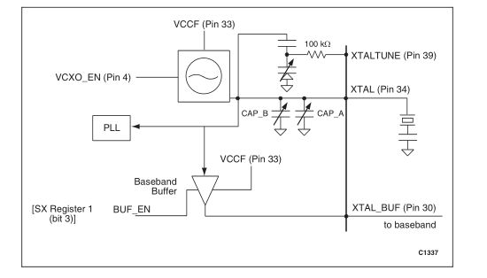
Figure 7. VCXO Block Diagram
Page 15
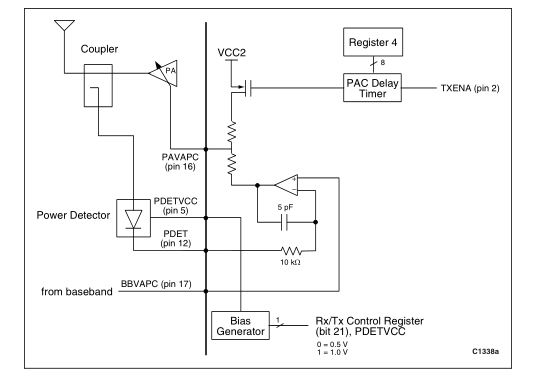
Figure 8. PA Controller Block Diagram
Table 3. CX74063-26 Absolute Maximum Ratings
Parameter
Minimum
Maximum
Units
| Supply voltage (VCC) | –0.3 | +3.6 | V |
| Ambient operating temperature range | –40 | +95 | °C |
| Storage temperature range | –50 | +125 | °C |
| Input voltage range | GND | VCC | V |
| Maximum power dissipation | 600 | mW |
Note: Stresses above these absolute maximum ratings may cause permanent damage. These are stress ratings only and functional operation at these conditions is not implied. Exposure to maximum rating conditions for extended periods may reduce device reliability.
Table 4. CX74063-26 Recommended Operating Conditions
Parameter
Minimum
Typical Maximum
Units
| LNA input level (pins 9, 11, 13) RXEN = Off | 10 | dBm | ||
| Power supply | 2.6 | 2.8 | 3.3 | V |
| Digital power supply, VDDBB | 1.8 | 3.3 | V | |
| Operating junction temperature | –40 | +110 | °C | |
| Operating ambient temperature | –30 | +85 | °C |
Page 16
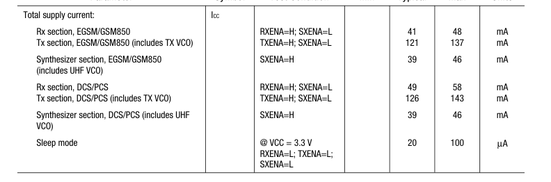
Table 5. Power Consumption Specifications (TA = 25° C, VCC = 2.8 V unless otherwise noted)
Parameter
Symbol
Test Condition
Min Typical Max
Units
Page 17
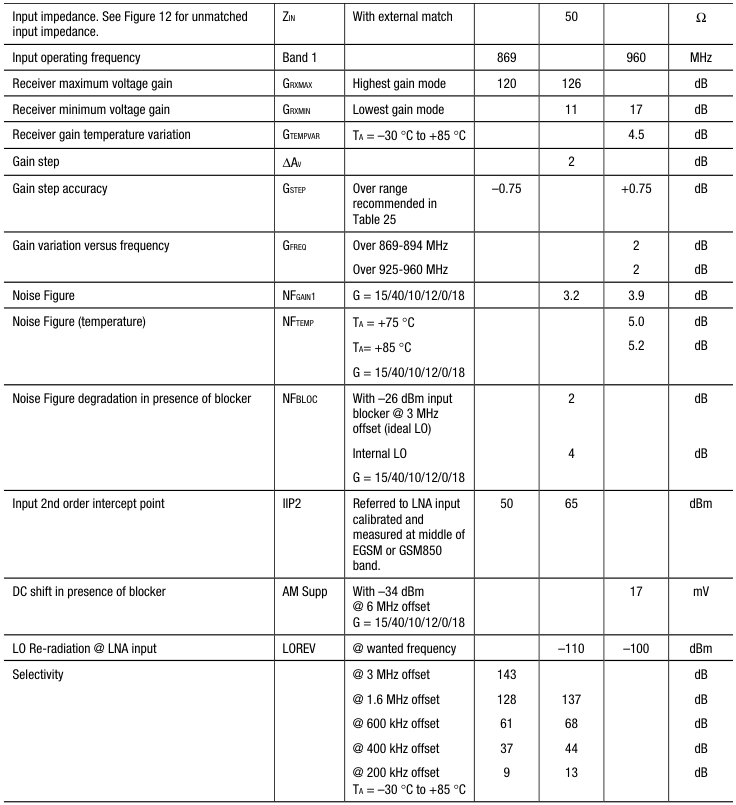
Table 6. CX74063-26 Electrical Specifications – EGSM/GSM850 Receiver (1 of 3)
(TA = 25° C, VCC = 2.8 V unless otherwise noted)
Parameter
Symbol
Test Condition
Min Typical Max
Units
(Note 1)
Page 18
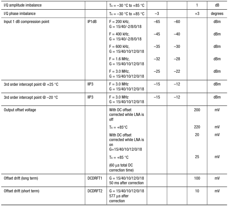
Table 6. CX74063-26 Electrical Specifications – EGSM/GSM850 Receiver (2 of 3)
(TA = 25° C, VCC = 2.8 V unless otherwise noted)
Parameter
Symbol
Test Condition
Min Typical Max
Units
(Note 1)
Baseband Tunable Active Filter
| 3 dB corner frequency (tunable) | FC | 80 | 100 | kHz | ||
| Corner frequency variation | dFC | 39.2 kΩ at pin 29 470 pF at pins 25-26 and 27-28 | –11 | +11 | % |
Page 19
Table 6. CX74063-26 Electrical Specifications – EGSM/GSM850 Receiver (3 of 3)
(TA = 25° C, VCC = 2.8 V unless otherwise noted)
Parameter
Symbol
Test Condition
Min Typical Max
Units
(Note 1)
Receiver Output Stage
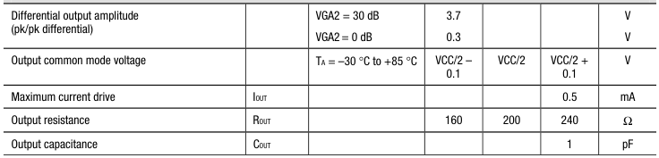
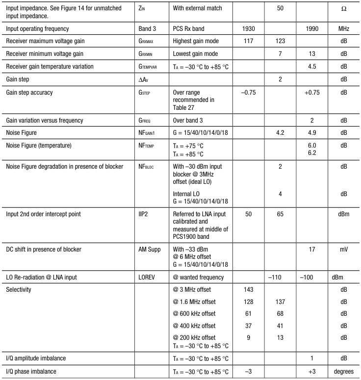
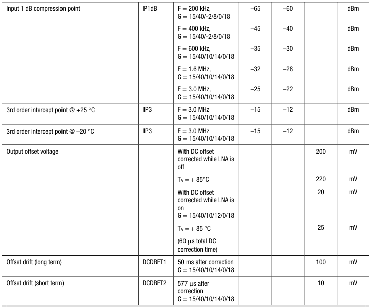
Note 1: Gain codes refer to LNA/Mixer/LPF1/VGA1/AUX/VGA2 gains in dB.
Table 7. CX74063-26 Electrical Specifications – DCS1800 Receiver (1 of 3) (TA = 25° C, VCC = 2.8 V unless otherwise noted)
Parameter
Symbol
Test Condition
Min Typical Max
Units
(Note 1)
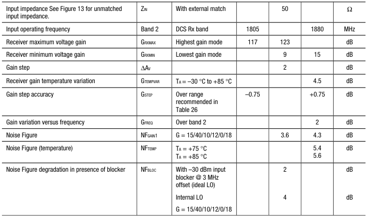
Page 20
Table 7. CX74063-26 Electrical Specifications – DCS1800 Receiver (2 of 3) (TA = 25° C, VCC = 2.8 V unless otherwise noted)
Parameter
Symbol
Test Condition
Min Typical Max
Units
(Note 1)
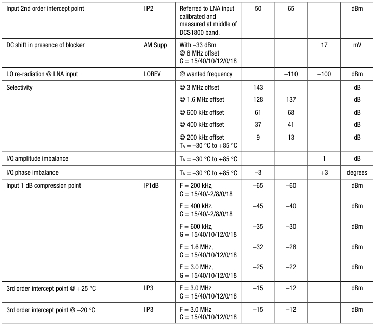
Page 21
Table 7. CX74063-26 Electrical Specifications – DCS1800 Receiver (3 of 3) (TA = 25° C, VCC = 2.8 V unless otherwise noted)
Parameter
Symbol
Test Condition
Min Typical Max
Units
(Note 1)
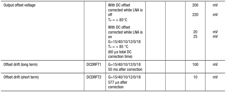
Baseband Tunable Active Filter
| 3 dB corner frequency (tunable) | FC | 80 | 100 | kHz | ||
| Corner frequency variation | dFC | 39.2 kΩ at pin 29 470 pF at pins 25-26 and 27-28 | –11 | +11 | % |
Receiver Output Stage
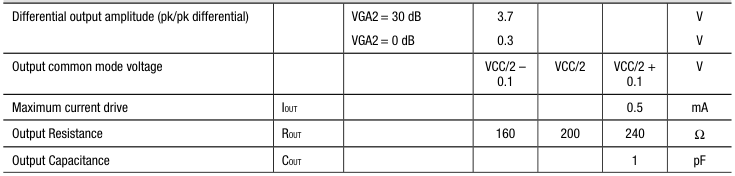
Note 1: Gain codes refer to LNA/Mixer/LPF1/VGA1/AUX/VGA2 gains in dB.
Page 22
Table 8. CX74063-26 Electrical Specifications – PCS1900 Receiver (1 of 3) (TA =2 5° C, VCC = 2.8 V unless otherwise noted)
Parameter
Symbol
Test Condition
Min Typical Max
Units
(Note 1)
Page 23
Table 8. CX74063-26 Electrical Specifications – PCS1900 Receiver (2 of 3) (TA =2 5° C, VCC = 2.8 V unless otherwise noted)
Parameter
Symbol
Test Condition
Min Typical Max
Units
(Note 1)
Baseband Tunable Active Filter
| 3 dB corner frequency (tunable) | FC | 80 | 100 | kHz | ||
| Corner frequency variation | dFC | 39.2 kΩ at pin 29 470 pF at pins 25-26 and 27-28 | –11 | +11 | % |
Page 24
Table 8. CX74063-26 Electrical Specifications – PCS1900 Receiver (3 of 3) (TA =2 5° C, VCC = 2.8 V unless otherwise noted)
Parameter
Symbol
Test Condition
Min Typical Max
Units
(Note 1)
Receiver Output Stage
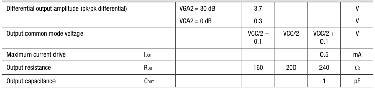
Note 1: Gain codes refer to LNA/Mixer/LPF1/VGA1/AUX/VGA2 gains in dB.
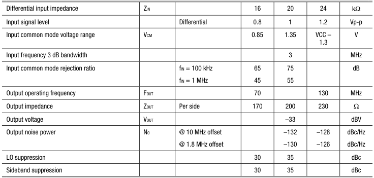
Table 9. CX74063-26 Electrical Specifications – Transmitter (1 of 4) (TA = 25° C, VCC = 2.8 V unless otherwise noted)
Parameter
Symbol
Test Condition
Min Typical Max
Units
I/Q Modulator
Translational Loop
| Spurious | Modulation 2nd order Modulation 3rd order | –70 –60 | –40 –55 | dBc dBc | ||
| Transmit frequency (input from VCO) | FTX | 800 | 2000 | MHz | ||
| IF frequency | FIF | 70 | 130 | MHz | ||
| Transmit input power | PIN | With external 50 Ω termination | –20 | –15 | –10 | dBm |
Page 25
Table 9. CX74063-26 Electrical Specifications – Transmitter (2 of 4) (TA = 25° C, VCC = 2.8 V unless otherwise noted)
Parameter
Symbol
Test Condition
Min Typical Max
Units
Translational Loop (continued)
| Transmit input impedance | ZIN | 300// 0.3 | Ω// pF | |||
| Transmitter output phase noise (includes TX VCO and LO PLL) | NO | @ 400 kHz offset @ 1.8 MHz offset @ 10 MHz offset EGSM/GSM850 @ 20 MHz offset EGSM/GSM850 @ 20 MHz offset DCS/PCS | –120 –130 –152 –164 –156 | –118 –124 –150 –162 –154 | dBc/Hz dBc/Hz dBc/Hz dBc/Hz dBc/Hz | |
| Tx phase error | TxPHERR | rms (employs reference frequency source, and loop filters as shown in the reference design) | 2.0 | degrees | ||
| Charge pump output current: high impedance source/sink | IOUT | RX/TX control register bits S15 S14 CP = 0 0 CP = 0 1 CP = 1 0 CP = 1 1 | ±0.5 ±0.75 ±1.0 ±1.25 | mA mA mA mA | ||
| Charge pump current variation | 0.3 ≤ VCPO ≤ VCC – 0.5 | 20 | % | |||
| Charge pump current variation over temperature | 0.3 ≤ VCPO ≤ VCC – 0.5 TA = –30 °C to +85 °C | 10 | % | |||
| D1 divide ratio range | 9 | 12 | ||||
| D2 divide ratio | 1 | 2 | ||||
| Tx mixer LO leakage | TXMIX LEAKAGE | Tx mixer 50 Ω terminated | –60 | dBm |
Low Band Translation Loop VCO
| Center frequency | fC | TA = –30 °C to +85 °C | 800 | 930 | MHz | |
| Digital frequency centering resolution | eDFC | 2.5 | MHz | |||
| Digital frequency centering time | tDFC | From rising edge of TXENA (13 MHz clock frequency) | 12 | 20 | µs | |
| Digital frequency centering voltage | VDFC | (Control voltage at end of DFC and start of analog lock) | VCC/2 – 0.2 | VCC/2 | VCC/2 + 0.2 | V |
| Analog frequency control range | fMAX -fMIN | 0.5 < VCTL < 2.2 | 20 | MHz |
Page 26
Table 9. CX74063-26 Electrical Specifications – Transmitter (3 of 4) (TA = 25° C, VCC = 2.8 V unless otherwise noted)
Parameter
Symbol
Test Condition
Min Typical Max
Units
Low Band Translation Loop VCO (continued)
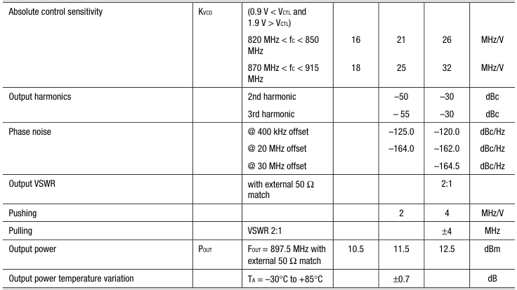
High Band Translation Loop VCO
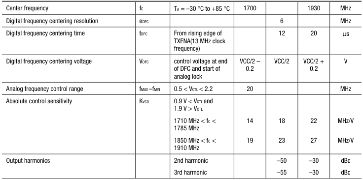
Page 27
Table 9. CX74063-26 Electrical Specifications – Transmitter (4 of 4) (TA = 25° C, VCC = 2.8 V unless otherwise noted)
Parameter
Symbol
Test Condition
Min Typical Max
Units
High Band Translation Loop VCO (continued)
| Phase noise | @ 400 kHz offset @ 20 MHz offset @ 30 MHz offset | –125.0 –158.0 | –120.0 –155.0 –164.5 | dBc/Hz dBc/Hz dBc/Hz | ||
| Output VSWR | with external 50 Ω match | 2:1 | ||||
| Pushing | 2 | 4 | MHz/V | |||
| Pulling | VSWR 2:1 | ±4 | MHz | |||
| Output power | POUT | FOUT= 1747.5 MHz with external 50 Ω match | 5.5 | 7 | 8.5 | dBm |
| Output power variation | TA = –30 °C to +85 °C | ±1 | dB |
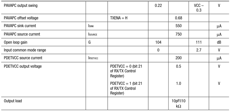
PA Gain Controller
Page 28
Table 10. CX74063-26 Electrical Specifications – Synthesizer (1 of 3) (TA = 25° C, VCC = 2.8 V unless otherwise noted)
Parameter
Symbol
Test Condition
Min Typical Max
Units
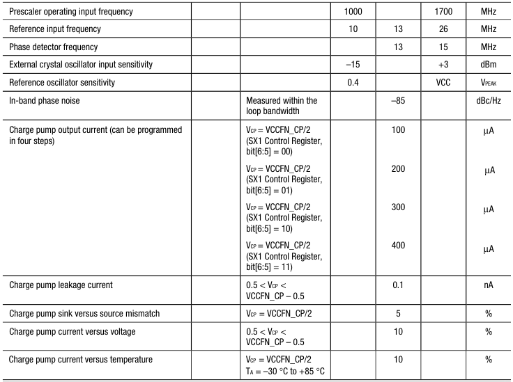
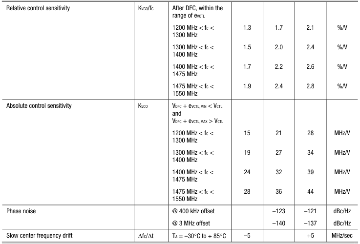
UHF VCO
| Center frequency | fC | TA = –30 °C to +85 °C | 1200 | 1550 | MHz | |
| Digital frequency centering resolution | eDFC | 2 | MHz | |||
| Digital frequency centering time | tDFC | From rising edge of SXENA or LE when programming SX word (13 MHz clock frequency) | 12 | 20 | µs | |
| Digital frequency centering voltage | VDFC | control voltage at end of DFC/start of analog lock | VCCUHF/2 – 0.2 | VCCUHF/2 | VCCUHF/2 + 0.2 | V |
| Analog frequency control range | fMAX -fMIN | 0.5 < VCTL < 2.2 | 30 | MHz |
Page 29
Table 10. CX74063-26 Electrical Specifications – Synthesizer (2 of 3) (TA = 25° C, VCC = 2.8 V unless otherwise noted)
Parameter
Symbol
Test Condition
Min Typical Max
Units
UHF VCO (continued)
26 MHz Crystal Oscillator
| Operating frequency | 26 | MHz | ||||
| Buffer output frequency | 26 | MHz | ||||
| Phase noise: @ 100 Hz @ 1 kHz @ 10 kHz | –98 –127 –145 | dBc/Hz dBc/Hz dBc/Hz | ||||
| Clock jitter | 16 | ps | ||||
| Spurious rejection | –20 | –15 | dBc | |||
| Digital tuning (Note 1) | ±50 | ±70 | ppm | |||
| Analog tuning (Note 1) | VTUNE = 0.05 to 2.5 V | ±20 | ±23 | ppm | ||
| Analog varactor voltage range | 0 | VCC | V | |||
| Analog varactor DC impedance | 1 | MΩ | ||||
| Supply voltage dependence | 2.8 ± 0.1 V | 1 | 2 | ppm/V | ||
| Operating current (start) @ 26 MHz | 2600 | µA |
Page 30
Table 10. CX74063-26 Electrical Specifications – Synthesizer (3 of 3) (TA = 25° C, VCC = 2.8 V unless otherwise noted)
Parameter
Symbol
Test Condition
Min Typical Max
Units
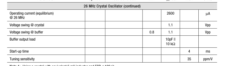
Note 1: Using a crystal with equivalent 6 mH inductor and ESR ≤ 100 Ω.
Table 11. CX74063-26 Electrical Specifications – Digital Interface (TA = 25° C, VCC = 2.8 V unless otherwise noted)
Parameter
Symbol
Test Condition
Min Typical Max
Units
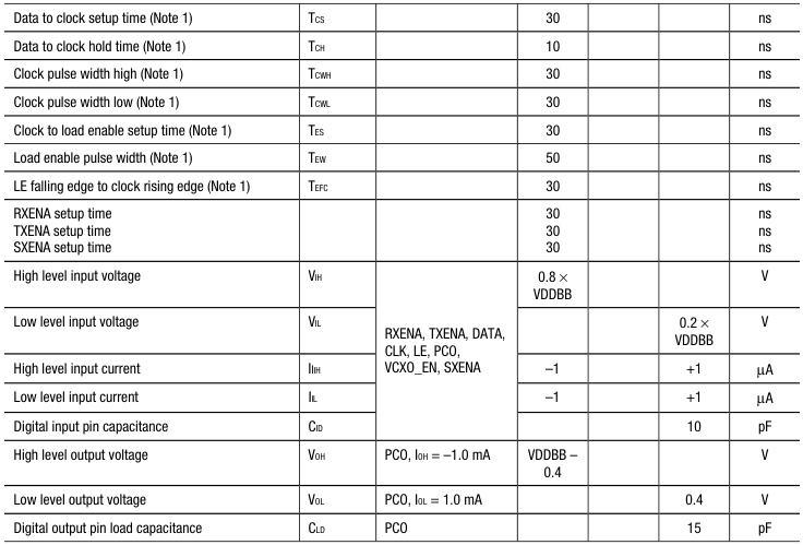
Note 1: See Figure 9.
Page 31
Serial Interface Programming
Table 12. Control and Output States
Register
Address Bits
| B6 | B5 | B4 | B3 | B2 | B1 | B0 | |
| SX1 Control | X | X | X | X | X | 0 | 0 |
| SX2 Fractional-N Modulo | X | X | X | X | X | 1 | 0 |
| RX/TX Control | X | X | X | X | X | 1 | 1 |
| R0 Auxiliary Control | X | X | X | 0 | 0 | 0 | 1 |
| R2 DC Offset Timing | X | X | X | 1 | 0 | 0 | 1 |
| R3 IP2 Calibration | X | 0 | 0 | 1 | 1 | 0 | 1 |
| R4 PAC Timing Control | X | 0 | 1 | 1 | 1 | 0 | 1 |
| R6 VCXO Control | 0 | 1 | 0 | 1 | 1 | 0 | 1 |
| R7 VCXO Control | 1 | 1 | 0 | 1 | 1 | 0 | 1 |
Table 13. SX1 Control Register (Synthesizer Control Functions)
Symbol
Function
State Description
| ADDR | Address bits [1:0]. Must be set to 00b (see Table 12) | |
| EN | Enable mode [2] | 0 enables synthesizer 1 disables synthesizer |
| BUF_EN | Buffer enable [3] | 0 sets buffer to off state 1 sets buffer to on state |
| SP | Phase detector output polarity [4] | 0 sets phase detector output for negative VCO gain 1 sets phase detector output for positive VCO gain |
| SC | Charge pump output current [6:5] | Bit [6,5]: 0 0 sets charge pump current to 100 µA 0 1 sets charge pump current to 200 µA 1 0 sets charge pump current to 300 µA 1 1 sets charge pump current to 400 µA |
| RSVD | Reserved | Bit [8,7]: set bit 8 = 1, bit 7 = 0 |
| N | Main divider [19:9] | Sets 11-bit main divider ratio range (64…2047) |
| R | Reference divider [23:20] | Sets 4-bit reference divider ratio range (1…15) |
Page 32
Table 14. SX2 Fractional-N Modulo Register
Symbol
Function
State Description
| ADDR | Address bits [1:0]. Must be set to 10b (see Table 12) | |
| FN | Fractional-N modulo [23:2] | Sets fractional-N modulo up to 222 range (0…4,194,303) |
Table 15. RX/TX Control Register (1 of 2)
Symbol
Function
State Description
| ADDR | Address bits [1:0]. Must be set to 11b (see Table 12) | |
| LNA | LNA gain step control [2] | 0 selects low gain mode of LNA 1 selects high gain mode of LNA |
| MIX | Mixer gain step [3] | 0 selects low gain mode of RX mixer 1 selects high gain mode of RX mixer |
| LPF1 | 1st LPF gain step [4] | 0 selects low gain mode of the first active LPF 1 selects high gain mode of the first active LPF |
| VGA2 | VGA2 gain steps [7:5] | Bit 7 to bit 5 program the VGA2 gain in 6 dB increments: Bit 7, Bit 6, Bit 5 0 0 0 sets the gain to 30 dB 0 0 1 sets the gain to 24 dB 0 1 0 sets the gain to 18 dB 0 1 1 sets the gain to 12 dB 1 0 0 sets the gain to 6 dB 1 0 1 sets the gain to 0 dB 1 1 0 not used 1 1 1 not used |
| AUX | Auxiliary gain [8] | 0 sets 0 dB auxiliary gain post gmC filter 1 sets 6 dB auxiliary gain post gmC filter |
| VGA1 | VGA1 gain steps [11:9] | Bit 11 to bit 9 program the VGA1 gain in the following increments: Bit 11, Bit 10, Bit 9 0 0 0 sets the gain to 0 dB 0 0 1 sets the gain to 24 dB 0 1 0 sets the gain to 12 dB 0 1 1 not used 1 0 0 sets the gain to 6 dB 1 0 1 sets the gain to 30 dB 1 1 0 sets the gain to 18 dB 1 1 1 not used |
| VGA1FINE | VGA1 fine gain step [13:12] | Bit 13 and bit 12 program VGA1 in 2 dB increments: Bit 13, Bit 12 0 0 sets gain to 0 dB 0 1 sets gain to 4 dB 1 0 sets gain to 2 dB 1 1 not used |
Page 33
Table 15. RX/TX Control Register (2 of 2)
Symbol
Function
State Description
| TXCP | TX charge pump bits [15:14] | Translational loop charge pump current setting: Bit 15, Bit 14 0 0 sets TXCP to 0.5 mA 0 1 sets TXCP to 0.75 mA 1 0 sets TXCP to 1.0 mA 1 1 sets TXCP to 1.25 mA |
| TXD1 | TX divider D1 [17:16] | Translational loop D1 divider setting: Bit 17, Bit 16 0 0 sets D1 to 9 0 1 sets D1 to 11 1 0 sets D1 to 10 1 1 sets D1 to 12 |
| TXD2 | TX divider D2 [18] | Translational loop D2 divider setting: 0 sets D2 to 1 1 sets D2 to 2 |
| PDETVCC | Power detector bias [19] | Bit [19] sets bias voltage for the Schottky diode pair: 0 = 0.5 V 1 = 1.0 V |
| SOFTSEL | Software band select [21:20] | Bit 21, Bit 20 0 0 not used 0 1 selects EGSM/GSM850, PCO = 0 1 0 selects DCS, PCO = 1 1 1 selects PCS, PCO = 1 |
| PREENA | Load default words [22] | 0 allows changing contents of R0 to R7 1 allows loading default words into R0 to R7 Upon power up, program RX/TX control register with PREENA = 1 to load the default words into R0 to R5. If changing the default words is required, program RX/TX control register with PREENA = 0 and then program any or all of R0 to R5. PREENA should also be set to 0 when sending SX R1, SX R2, and RX/TX control register words before each time slot in normal operation. The data is stored in R0 to R5 as long as VDDBB (pin 43) is supplied with power. |
| NU | Not used [23] | Not used |
Page 34
Table 16. R0 Auxiliary Control Register
Symbol
Function
State Description
Default (Binary)
| ADDR | Address bits [3:0]. Must be set to 0001b (see Table 12) | ||
| GMC_BYP | Bypass GMC stage [4] | 0 enables gmC filter stage 1 disables and bypasses gmC filter stage | 0 |
| SK_BYP | Bypass S-K stage [5] | 0 enables Sallen-Key filter stage 1 disables and bypasses Sallen-Key filter stage | 0 |
| DC_BYP1 | Bypass first DC OC loop [6] | 0 enables first DC offset correction loop 1 disables and bypasses first DC offset correction loop | 0 |
| DC_BYP2 | Bypass second DC OC loop [7] | 0 enables second DC offset correction loop 1 disables and bypasses second DC offset correction | 0 |
| DC_BYP3 | Bypass second DC OC loop [8] | 0 enables third DC offset correction loop 1 disables and bypasses third DC offset correction | 0 |
| NU | Not used [9] | Not used | 0 |
| TVCOEN | TXVCO Select [10] | 0 disables TXVCO 1 enables TXVCO via TXENA (Pin4) | 1 |
| RSVD | Reserved [12:11] | Reserved, must be programmed to default value | 10 |
| NU | Not Used [13] | Not Used | 0 |
| RSVD | Reserved [14] | Reserved, must be programmed to default value | 0 |
| RSVD | Reserved [15] | Reserved, must be programmed to default value | 0 |
| DFCPLLENA | DFC Enable [16] | 0 disables DFC 1 enables DFC | 1 |
| UHFVCOENA | UHFVCO Enable [17] | 0 disables internal UHF VCO 1 enables internal UHF VCO | 1 |
| RSVD | Reserved[20:18] | Reserved, must be programmed to default value | 011 |
| CALENA | Enable IP2 Cal [21] | 0 disables IP2 calibration 1 enables IP2 calibration | 1 |
| NU | Not used[22] | Not used | 0 |
| NU | Not used[23] | Not used | 0 |
Page 35
Table 17. R2 DC Offset Timing Register
Symbol
Function
State Description
Default (Binary)
| ADDR | Address bits [3:0]. Must be set to 1001b (see Table 12) | ||
| DCOCL1 | DCOC control [7:4] | Tracking timing for DCOC1 (tT_H1 = (DCOCL1 x 64 x R)/Fref ) (Note 1) | 0100 (20 µs with 13 MHz f REF) |
| DCOCL2 | DCOC control [12:8] | Tracking timing for DCOC2 (tT_H2 = (DCOCL2 x 64 x R)/Fref ) (Note 1) | 01100 (60 µs with 13 MHz f REF) |
| DCOCL3 | DCOC control [16:13] | Tracking timing for DCOC3 (tT_H3 = (DCOCL3 x 128 x R)/Fref ) (Note 1) | 0110 (60 µs with 13 MHz f REF) |
| FEENA_TIM | FEENA relative to initial track [20:17] | Front end enable timing (tFEENA = (FEENA_TIM x 128 x R)/Fref ) (Note 1) | 0100 (40 µs with 13 MHz f REF) |
| NU | Not used [21] | Not used | 0 |
| NU | Not used [22] | Not used | 0 |
| NU | Not used [23] | Not used | 0 |
Note 1: See Figure 3 and Figure 4.
Table 18. R3 IP2 Calibration Register
Symbol
Function
State Description
| ADDR | Address bits [5:0]. Must be set to 001101b (see Table 12) | |
| ADDR_SEL | Channel selection [6] | 0 selects Q channel 1 selects I channel |
| RSVD | Reserved [7] | Must be set to 1 for correct operation |
| CORR_DATA | IP2 correction coefficient [15:8] | Coefficient for adjustment of receiver IP2: Bit [15] sets polarity: 0 = Positive 1 = Negative Bit [14:8]: 1111111 minimum correction • • • 0000000 maximum correction Bit [14] = MSB Bit [8] = LSB |
| NU | Not used [23:16] | Not used |
Page 36
Table 19. R4 PAC Timing Control Register
Symbol
Function
State Description
Default (Binary)
| ADDR | Address bits [5:0]. Must be set to 011101b (see Table 12) | ||
| RSVD | Reserved [11:6] | Reserved. Must be set to default value. | 000010 |
| PAC_TIME | PAC timing control [19:12] | Bit [19:12] sets timing for the PAC pedestal. When all bits = 0, no pedestal. Bit [12] = MSB = 1024/fPFD = 78.7 µs for fPFD = 13 MHz Bit [19] = LSB = 8/fPFD = 0.615 µs for fPFD = 13 MHz | 10011010 = 54.769 µs |
| RSVD | Reserved [23:20] | Reserved. Must be set to default value. | 0100 |
Table 20. R6 VCXO Control Register
Symbol
Function Description
Internal Power-
Recommended
On Value
Operational Value
(Binary)
(Binary)
| ADDR | Address bits [6:0]. Must be set to 0101101b (see Table 12) | ||
| CAP_A | Bit [11:7] capacitor A array control. Binary weighted. Bit [11] = LSB = 1/8 pF Bit [7] = MSB = 2 pF Array composition = 2 pF, 1 pF, 0.5 pF, 0.25 pF, 0.125 pF | 00001 | Determined during a one- time factory calibration |
| CAP_B | Bit [15:12] capacitor B array control. Binary weighted. Bit [15] = LSB = 1/32 pF Bit [12] = MSB = 1/4 pF Array composition = 0.25 pF, 0.125 pF, 0.065 pF, 0.03125 pF | 0000 | |
| RSVD | Bit [23:16] reserved | 00000000 | 00000000 |
Note: Programmed values in this register are not maintained with VDDBB (pin 43).
Page 37
Table 21. R7 VCXO Control Register
Symbol
Function Description
Internal Power-
Recommended
On Value
Operational Value
(Binary)
(Binary)
| ADDR | Address bits [6:0]. Must be set to 1101101b (see Table 12) | ||
| I_VCXO | Bit [10:7] negative resistance current control. Binary weighted. Negative logic (on = low, off = high) Bit [10] = LSB = 8 µA Bit [7] = MSB = 64 µA Stepped values = 64 µA, 32 µA, 16 µA, 8 µA | 0101 | 1001 |
| RSVD | Bit [23:11] reserved. Must be set to default value. | 0000000000000 | 0000000001110 (Must Use) |
Note: Programmed values in this register are not maintained with VDDBB (pin 43).
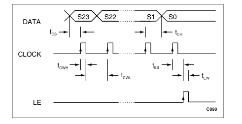
Figure 9. Serial Data Input Timing Diagram For Transceiver
Page 38
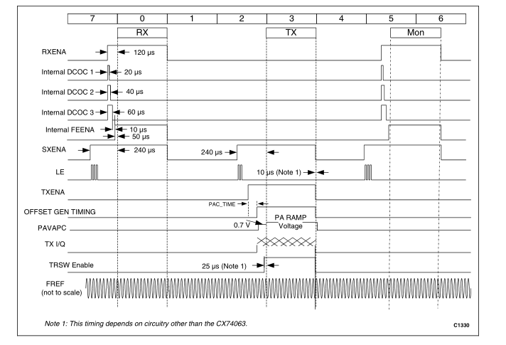
Figure 10. CX74063-26 Signal Timing Example (Normal Operation)
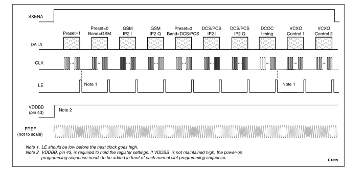
Figure 11. CX74063-26 Register Programming Sequence and Timing Example (Initialization After Power Up)
Page 39
Receiver Data
Table 22. Recommended EGSM900/GSM850 AGC Data (1 of 2) (AGC Setpoint = - 25.2 dBV = 55.0 mVrms)
Internal
Antenna Input External
I/Q Output Total Inter-
(dBm)
Front
(dBV)
voltage
LNA Mixer LPF VGA1
VGA1 Aux VGA2
stage
End
Gain
(dB) (dB) (dB) (dB)
Fine (dB) (dB) (dB)
Losses
Losses
From To
From To
(dB) (dB)
(dB)
| –110 | –108 | –4.0 | 15 | 40 | 10 | 18 | 4 | 0 | 18 | –4.2 | 96.8 | –26.2 | –24.2 |
| –108 | –106 | –4.0 | 15 | 40 | 10 | 18 | 2 | 0 | 18 | –4.2 | 94.8 | –26.2 | –24.2 |
| –106 | –104 | –4.0 | 15 | 40 | 10 | 18 | 0 | 0 | 18 | –4.2 | 92.8 | –26.2 | –24.2 |
| –104 | –102 | –4.0 | 15 | 40 | 10 | 12 | 4 | 0 | 18 | –4.2 | 90.8 | –26.2 | –24.2 |
| –102 | –100 | –4.0 | 15 | 40 | 10 | 12 | 2 | 0 | 18 | –4.2 | 88.8 | –26.2 | –24.2 |
| –100 | –98 | –4.0 | 15 | 40 | 10 | 12 | 0 | 0 | 18 | –4.2 | 86.8 | –26.2 | –24.2 |
| –98 | –96 | –4.0 | 15 | 40 | 10 | 6 | 4 | 0 | 18 | –4.2 | 84.8 | –26.2 | –24.2 |
| –96 | –94 | –4.0 | 15 | 40 | 10 | 6 | 2 | 0 | 18 | –4.2 | 82.8 | –26.2 | –24.2 |
| –94 | –92 | –4.0 | 15 | 40 | 10 | 6 | 0 | 0 | 18 | –4.2 | 80.8 | –26.2 | –24.2 |
| –92 | –90 | –4.0 | 15 | 40 | 10 | 0 | 4 | 0 | 18 | –4.2 | 78.8 | –26.2 | –24.2 |
| –90 | –88 | –4.0 | 15 | 40 | 10 | 0 | 2 | 0 | 18 | –4.2 | 76.8 | –26.2 | –24.2 |
| –88 | –86 | –4.0 | 15 | 40 | 10 | 0 | 0 | 0 | 18 | –4.2 | 74.8 | –26.2 | –24.2 |
| –86 | –84 | –4.0 | 15 | 40 | –2 | 6 | 4 | 0 | 18 | –4.2 | 72.8 | –26.2 | –24.2 |
| –84 | –82 | –4.0 | 15 | 40 | –2 | 6 | 2 | 0 | 18 | –4.2 | 70.8 | –26.2 | –24.2 |
| –82 | –80 | –4.0 | 15 | 40 | –2 | 6 | 0 | 0 | 18 | –4.2 | 68.8 | –26.2 | –24.2 |
| –80 | –78 | –4.0 | 15 | 40 | –2 | 0 | 4 | 0 | 18 | –4.2 | 66.8 | –26.2 | –24.2 |
| –78 | –76 | –4.0 | 15 | 40 | –2 | 0 | 2 | 0 | 18 | –4.2 | 64.8 | –26.2 | –24.2 |
| –76 | –74 | –4.0 | 15 | 40 | –2 | 0 | 0 | 0 | 18 | –4.2 | 62.8 | –26.2 | –24.2 |
| –74 | –72 | –4.0 | 15 | 22 | 10 | 0 | 4 | 0 | 18 | –4.2 | 60.8 | –26.2 | –24.2 |
| –72 | –70 | –4.0 | 15 | 22 | 10 | 0 | 2 | 0 | 18 | –4.2 | 58.8 | –26.2 | –24.2 |
| –70 | –68 | –4.0 | 15 | 22 | 10 | 0 | 0 | 0 | 18 | –4.2 | 56.8 | –26.2 | –24.2 |
| –68 | –66 | –4.0 | 15 | 22 | –2 | 6 | 4 | 0 | 18 | –4.2 | 54.8 | –26.2 | –24.2 |
| –66 | –64 | –4.0 | 15 | 22 | –2 | 6 | 2 | 0 | 18 | –4.2 | 52.8 | –26.2 | –24.2 |
| –64 | –62 | –4.0 | 15 | 22 | –2 | 6 | 0 | 0 | 18 | –4.2 | 50.8 | –26.2 | –24.2 |
| –62 | –60 | –4.0 | 15 | 22 | –2 | 0 | 4 | 0 | 18 | –4.2 | 48.8 | –26.2 | –24.2 |
| –60 | –58 | –4.0 | 15 | 22 | –2 | 0 | 2 | 0 | 18 | –4.2 | 46.8 | –26.2 | –24.2 |
| –58 | –56 | –4.0 | 15 | 22 | –2 | 0 | 0 | 0 | 18 | –4.2 | 44.8 | –26.2 | –24.2 |
| –56 | –54 | –4.0 | –5 | 22 | 10 | 6 | 0 | 0 | 18 | –4.2 | 42.8 | –26.2 | –24.2 |
| –54 | –52 | –4.0 | –5 | 22 | 10 | 0 | 4 | 0 | 18 | –4.2 | 40.8 | –26.2 | –24.2 |
Page 40
Table 22. Recommended EGSM900/GSM850 AGC Data (2 of 2) (AGC Setpoint = - 25.2 dBV = 55.0 mVrms)
Internal
Antenna Input External
I/Q Output Total Inter-
(dBm)
Front
(dBV)
voltage
LNA Mixer LPF VGA1
VGA1 Aux VGA2
stage
End
Gain
(dB) (dB) (dB) (dB)
Fine (dB) (dB) (dB)
Losses
Losses
From To
From To
(dB) (dB)
(dB)
| –52 | –50 | –4.0 | –5 | 22 | 10 | 0 | 2 | 0 | 18 | –4.2 | 38.8 | –26.2 | –24.2 |
| –50 | –48 | –4.0 | –5 | 22 | 10 | 0 | 0 | 0 | 18 | –4.2 | 36.8 | –26.2 | –24.2 |
| –48 | –46 | –4.0 | –5 | 22 | –2 | 6 | 4 | 0 | 18 | –4.2 | 34.8 | –26.2 | –24.2 |
| –46 | –44 | –4.0 | –5 | 22 | –2 | 6 | 2 | 0 | 18 | –4.2 | 32.8 | –26.2 | –24.2 |
| –44 | –42 | –4.0 | –5 | 22 | –2 | 6 | 0 | 0 | 18 | –4.2 | 30.8 | –26.2 | –24.2 |
| –42 | –40 | –4.0 | –5 | 22 | –2 | 0 | 4 | 0 | 18 | –4.2 | 28.8 | –26.2 | –24.2 |
| –40 | –38 | –4.0 | –5 | 22 | –2 | 0 | 2 | 0 | 18 | –4.2 | 26.8 | –26.2 | –24.2 |
| –38 | –36 | –4.0 | –5 | 22 | –2 | 0 | 0 | 0 | 18 | –4.2 | 24.8 | –26.2 | –24.2 |
| –36 | –34 | –4.0 | –5 | 22 | –2 | 0 | 4 | 0 | 12 | –4.2 | 22.8 | –26.2 | –24.2 |
| –34 | –32 | –4.0 | –5 | 22 | –2 | 0 | 2 | 0 | 12 | –4.2 | 20.8 | –26.2 | –24.2 |
| –32 | –30 | –4.0 | –5 | 22 | –2 | 0 | 0 | 0 | 12 | –4.2 | 18.8 | –26.2 | –24.2 |
| –30 | –28 | –4.0 | –5 | 22 | –2 | 0 | 4 | 0 | 6 | –4.2 | 16.8 | –26.2 | –24.2 |
| –28 | –26 | –4.0 | –5 | 22 | –2 | 0 | 2 | 0 | 6 | –4.2 | 14.8 | –26.2 | –24.2 |
| –26 | –24 | –4.0 | –5 | 22 | –2 | 0 | 0 | 0 | 6 | –4.2 | 12.8 | –26.2 | –24.2 |
| –24 | –22 | –4.0 | –5 | 22 | –2 | 0 | 4 | 0 | 0 | –4.2 | 10.8 | –26.2 | –24.2 |
| –22 | –20 | –4.0 | –5 | 22 | –2 | 0 | 2 | 0 | 0 | –4.2 | 8.8 | –26.2 | –24.2 |
| –20 | –18 | –4.0 | –5 | 22 | –2 | 0 | 0 | 0 | 0 | –4.2 | 6.8 | –26.2 | –24.2 |
| –18 | –16 | –4.0 | –5 | 22 | –2 | 0 | 0 | 0 | 0 | –4.2 | 6.8 | –24.2 | –22.2 |
| –16 | –14 | –4.0 | –5 | 22 | –2 | 0 | 0 | 0 | 0 | –4.2 | 6.8 | –22.2 | –20.2 |
Page 41
Table 23. Recommended DCS1800 AGC Data (1 of 2) (AGC Setpoint = - 24.2 dBV = 61.7 mVrms)
Internal
Antenna Input External
I/Q Output Total Inter-
(dBm)
Front
(dBV)
voltage
LNA Mixer LPF VGA1
VGA1 Aux VGA2
stage
End
Gain
(dB) (dB) (dB) (dB)
Fine (dB) (dB) (dB)
Losses
Losses
From To
From To
(dB) (dB)
(dB)
| –110 | –108 | –4.2 | 15 | 40 | 10 | 24 | 0 | 0 | 18 | –5.0 | 97.8 | –25.2 | –23.2 |
| –108 | –106 | –4.2 | 15 | 40 | 10 | 18 | 4 | 0 | 18 | –5.0 | 95.8 | –25.2 | –23.2 |
| –106 | –104 | –4.2 | 15 | 40 | 10 | 18 | 2 | 0 | 18 | –5.0 | 93.8 | –25.2 | –23.2 |
| –104 | –102 | –4.2 | 15 | 40 | 10 | 18 | 0 | 0 | 18 | –5.0 | 91.8 | –25.2 | –23.2 |
| –102 | –100 | –4.2 | 15 | 40 | 10 | 12 | 4 | 0 | 18 | –5.0 | 89.8 | –25.2 | –23.2 |
| –100 | –98 | –4.2 | 15 | 40 | 10 | 12 | 2 | 0 | 18 | –5.0 | 87.8 | –25.2 | –23.2 |
| –98 | –96 | –4.2 | 15 | 40 | 10 | 12 | 0 | 0 | 18 | –5.0 | 85.8 | –25.2 | –23.2 |
| –96 | –94 | –4.2 | 15 | 40 | 10 | 6 | 4 | 0 | 18 | –5.0 | 83.8 | –25.2 | –23.2 |
| –94 | –92 | –4.2 | 15 | 40 | 10 | 6 | 2 | 0 | 18 | –5.0 | 81.8 | –25.2 | –23.2 |
| –92 | –90 | –4.2 | 15 | 40 | 10 | 6 | 0 | 0 | 18 | –5.0 | 79.8 | –25.2 | –23.2 |
| –90 | –88 | –4.2 | 15 | 40 | 10 | 0 | 4 | 0 | 18 | –5.0 | 77.8 | –25.2 | –23.2 |
| –88 | –86 | –4.2 | 15 | 40 | 10 | 0 | 2 | 0 | 18 | –5.0 | 75.8 | –25.2 | –23.2 |
| –86 | –84 | –4.2 | 15 | 40 | 10 | 0 | 0 | 0 | 18 | –5.0 | 73.8 | –25.2 | –23.2 |
| –84 | –82 | –4.2 | 15 | 40 | –2 | 6 | 4 | 0 | 18 | –5.0 | 71.8 | –25.2 | –23.2 |
| –82 | –80 | –4.2 | 15 | 40 | –2 | 6 | 2 | 0 | 18 | –5.0 | 69.8 | –25.2 | –23.2 |
| –80 | –78 | –4.2 | 15 | 40 | –2 | 6 | 0 | 0 | 18 | –5.0 | 67.8 | –25.2 | –23.2 |
| –78 | –76 | –4.2 | 15 | 40 | –2 | 0 | 4 | 0 | 18 | –5.0 | 65.8 | –25.2 | –23.2 |
| –76 | –74 | –4.2 | 15 | 40 | –2 | 0 | 2 | 0 | 18 | –5.0 | 63.8 | –25.2 | –23.2 |
| –74 | –72 | –4.2 | 15 | 40 | –2 | 0 | 0 | 0 | 18 | –5.0 | 61.8 | –25.2 | –23.2 |
| –72 | –70 | –4.2 | 15 | 22 | 10 | 0 | 4 | 0 | 18 | –5.0 | 59.8 | –25.2 | –23.2 |
| –70 | –68 | –4.2 | 15 | 22 | 10 | 0 | 2 | 0 | 18 | –5.0 | 57.8 | –25.2 | –23.2 |
| –68 | –66 | –4.2 | 15 | 22 | 10 | 0 | 0 | 0 | 18 | –5.0 | 55.8 | –25.2 | –23.2 |
| –66 | –64 | –4.2 | 15 | 22 | 10 | 6 | 4 | 0 | 18 | –5.0 | 53.8 | –25.2 | –23.2 |
| –64 | –62 | –4.2 | 15 | 22 | –2 | 6 | 2 | 0 | 18 | –5.0 | 51.8 | –25.2 | –23.2 |
| –62 | –60 | –4.2 | 15 | 22 | –2 | 6 | 0 | 0 | 18 | –5.0 | 49.8 | –25.2 | –23.2 |
| –60 | –58 | –4.2 | 15 | 22 | –2 | 0 | 4 | 0 | 18 | –5.0 | 47.8 | –25.2 | –23.2 |
| –58 | –56 | –4.2 | 15 | 22 | –2 | 0 | 2 | 0 | 18 | –5.0 | 45.8 | –25.2 | –23.2 |
| –56 | –54 | –4.2 | 15 | 22 | –2 | 0 | 0 | 0 | 18 | –5.0 | 43.8 | –25.2 | –23.2 |
| –54 | –52 | –4.2 | –7 | 22 | 10 | 6 | 2 | 0 | 18 | –5.0 | 41.8 | –25.2 | –23.2 |
| –52 | –50 | –4.2 | –7 | 22 | 10 | 6 | 0 | 0 | 18 | –5.0 | 39.8 | –25.2 | –23.2 |
Page 42
Table 23. Recommended DCS1800 AGC Data (2 of 2) (AGC Setpoint = - 24.2 dBV = 61.7 mVrms)
Internal
Antenna Input External
I/Q Output Total Inter-
(dBm)
Front
(dBV)
voltage
LNA Mixer LPF VGA1
VGA1 Aux VGA2
stage
End
Gain
(dB) (dB) (dB) (dB)
Fine (dB) (dB) (dB)
Losses
Losses
From To
From To
(dB) (dB)
(dB)
| –50 | –48 | –4.2 | –7 | 22 | 10 | 0 | 4 | 0 | 18 | –5.0 | 37.8 | –25.2 | –23.2 |
| –48 | –46 | –4.2 | –7 | 22 | 10 | 0 | 2 | 0 | 18 | –5.0 | 35.8 | –25.2 | –23.2 |
| –46 | –44 | –4.2 | –7 | 22 | 10 | 0 | 0 | 0 | 18 | –5.0 | 33.8 | –25.2 | –23.2 |
| –44 | –42 | –4.2 | –7 | 22 | –2 | 6 | 4 | 0 | 18 | –5.0 | 31.8 | –25.2 | –23.2 |
| –42 | –40 | –4.2 | –7 | 22 | –2 | 6 | 2 | 0 | 18 | –5.0 | 29.8 | –25.2 | –23.2 |
| –40 | –38 | –4.2 | –7 | 22 | –2 | 6 | 0 | 0 | 18 | –5.0 | 27.8 | –25.2 | –23.2 |
| –38 | –36 | –4.2 | –7 | 22 | –2 | 0 | 4 | 0 | 18 | –5.0 | 25.8 | –25.2 | –23.2 |
| –36 | –34 | –4.2 | –7 | 22 | –2 | 0 | 2 | 0 | 18 | –5.0 | 23.8 | –25.2 | –23.2 |
| –34 | –32 | –4.2 | –7 | 22 | –2 | 0 | 0 | 0 | 18 | –5.0 | 21.8 | –25.2 | –23.2 |
| –32 | –30 | –4.2 | –7 | 22 | –2 | 0 | 4 | 0 | 12 | –5.0 | 19.8 | –25.2 | –23.2 |
| –30 | –28 | –4.2 | –7 | 22 | –2 | 0 | 2 | 0 | 12 | –5.0 | 17.8 | –25.2 | –23.2 |
| –28 | –26 | –4.2 | -7 | 22 | –2 | 0 | 0 | 0 | 12 | –5.0 | 15.8 | –25.2 | –23.2 |
| –26 | –24 | –4.2 | -7 | 22 | –2 | 0 | 4 | 0 | 6 | –5.0 | 13.8 | –25.2 | –23.2 |
| –24 | –22 | –4.2 | -7 | 22 | –2 | 0 | 2 | 0 | 6 | –5.0 | 11.8 | –25.2 | –23.2 |
| –22 | –20 | –4.2 | -7 | 22 | –2 | 0 | 0 | 0 | 6 | –5.0 | 9.8 | –25.2 | –23.2 |
| –20 | –18 | –4.2 | -7 | 22 | –2 | 0 | 4 | 0 | 0 | –5.0 | 7.8 | –25.2 | –23.2 |
| –18 | –16 | –4.2 | -7 | 22 | –2 | 0 | 2 | 0 | 0 | –5.0 | 5.8 | –25.2 | –23.2 |
| –16 | –14 | –4.2 | -7 | 22 | –2 | 0 | 0 | 0 | 0 | –5.0 | 5.8 | –23.2 | –21.2 |
Page 43
Table 24. Recommended PCS1900 AGC Data (1 of 2) (AGC Setpoint = - 25.4 dBV = 53.7 mVrms)
Internal
Antenna Input External
I/Q Output Total Inter-
(dBm)
Front
(dBV)
voltage
LNA Mixer LPF VGA1
VGA1 Aux VGA2
stage
End
Gain
(dB) (dB) (dB) (dB)
Fine (dB) (dB) (dB)
Losses
Losses
From To
From To
(dB) (dB)
(dB)
| –110 | –108 | –4.2 | 15 | 40 | 10 | 24 | 0 | 0 | 18 | –6.2 | 96.6 | –26.4 | –24.4 |
| –108 | –106 | –4.2 | 15 | 40 | 10 | 18 | 4 | 0 | 18 | –6.2 | 94.6 | –26.4 | –24.4 |
| –106 | –104 | –4.2 | 15 | 40 | 10 | 18 | 2 | 0 | 18 | –6.2 | 92.6 | –26.4 | –24.4 |
| –104 | –102 | –4.2 | 15 | 40 | 10 | 18 | 0 | 0 | 18 | –6.2 | 90.6 | –26.4 | –24.4 |
| –102 | –100 | –4.2 | 15 | 40 | 10 | 12 | 4 | 0 | 18 | –6.2 | 88.6 | –26.4 | –24.4 |
| –100 | –98 | –4.2 | 15 | 40 | 10 | 12 | 2 | 0 | 18 | –6.2 | 86.6 | –26.4 | –24.4 |
| –98 | –96 | –4.2 | 15 | 40 | 10 | 12 | 0 | 0 | 18 | –6.2 | 84.6 | –26.4 | –24.4 |
| –96 | –94 | –4.2 | 15 | 40 | 10 | 6 | 4 | 0 | 18 | –6.2 | 82.6 | –26.4 | –24.4 |
| –94 | –92 | –4.2 | 15 | 40 | 10 | 6 | 2 | 0 | 18 | –6.2 | 80.6 | –26.4 | –24.4 |
| –92 | –90 | –4.2 | 15 | 40 | 10 | 6 | 0 | 0 | 18 | –6.2 | 78.6 | –26.4 | –24.4 |
| –90 | –88 | –4.2 | 15 | 40 | 10 | 0 | 4 | 0 | 18 | –6.2 | 76.6 | –26.4 | –24.4 |
| –88 | –86 | –4.2 | 15 | 40 | 10 | 0 | 2 | 0 | 18 | –6.2 | 74.6 | –26.4 | –24.4 |
| –86 | –84 | –4.2 | 15 | 40 | 10 | 0 | 0 | 0 | 18 | –6.2 | 72.6 | –26.4 | –24.4 |
| –84 | –82 | –4.2 | 15 | 40 | –2 | 6 | 4 | 0 | 18 | –6.2 | 70.6 | –26.4 | –24.4 |
| –82 | –80 | –4.2 | 15 | 40 | –2 | 6 | 2 | 0 | 18 | –6.2 | 68.6 | –26.4 | –24.4 |
| –80 | –78 | –4.2 | 15 | 40 | –2 | 6 | 0 | 0 | 18 | –6.2 | 66.6 | –26.4 | –24.4 |
| –78 | –76 | –4.2 | 15 | 40 | –2 | 0 | 4 | 0 | 18 | –6.2 | 64.6 | –26.4 | –24.4 |
| –76 | –74 | –4.2 | 15 | 40 | –2 | 0 | 2 | 0 | 18 | –6.2 | 62.6 | –26.4 | –24.4 |
| –74 | –72 | –4.2 | 15 | 40 | –2 | 0 | 0 | 0 | 18 | –6.2 | 60.6 | –26.4 | –24.4 |
| –72 | –70 | –4.2 | 15 | 22 | 10 | 0 | 4 | 0 | 18 | –6.2 | 58.6 | –26.4 | –24.4 |
| –70 | –68 | –4.2 | 15 | 22 | 10 | 0 | 2 | 0 | 18 | –6.2 | 56.6 | –26.4 | –24.4 |
| –68 | –66 | –4.2 | 15 | 22 | 10 | 0 | 0 | 0 | 18 | –6.2 | 54.6 | –26.4 | –24.4 |
| –66 | –64 | –4.2 | 15 | 22 | –2 | 6 | 4 | 0 | 18 | –6.2 | 52.6 | –26.4 | –24.4 |
| –64 | –62 | –4.2 | 15 | 22 | –2 | 6 | 2 | 0 | 18 | –6.2 | 50.6 | –26.4 | –24.4 |
| –62 | –60 | –4.2 | 15 | 22 | –2 | 6 | 0 | 0 | 18 | –6.2 | 48.6 | –26.4 | –24.4 |
| –60 | –58 | –4.2 | 15 | 22 | –2 | 0 | 4 | 0 | 18 | –6.2 | 46.6 | –26.4 | –24.4 |
| –58 | –56 | –4.2 | 15 | 22 | –2 | 0 | 2 | 0 | 18 | –6.2 | 44.6 | –26.4 | –24.4 |
| –56 | –54 | –4.2 | 15 | 22 | –2 | 0 | 0 | 0 | 18 | –6.2 | 42.6 | –26.4 | –24.4 |
| –54 | –52 | –4.2 | –5 | 22 | 10 | 6 | 0 | 0 | 18 | –6.2 | 40.6 | –26.4 | –24.4 |
| –52 | –50 | –4.2 | –5 | 22 | 10 | 0 | 4 | 0 | 18 | –6.2 | 38.6 | –26.4 | –24.4 |
Page 44
Table 24. Recommended PCS1900 AGC Data (2 of 2) (AGC Setpoint = - 25.4 dBV = 53.7 mVrms)
Internal
Antenna Input External
I/Q Output Total Inter-
(dBm)
Front
(dBV)
voltage
LNA Mixer LPF VGA1 VGA1 Aux VGA2
stage
End
Gain
(dB) (dB) (dB) (dB) Fine (dB) (dB) (dB)
Losses
Losses
From To
From To
(dB) (dB)
(dB)
| –50 | –48 | –4.2 | –5 | 22 | 10 | 0 | 2 | 0 | 18 | –6.2 | 36.6 | –26.4 | –24.4 |
| –48 | –46 | –4.2 | –5 | 22 | 10 | 0 | 0 | 0 | 18 | –6.2 | 34.6 | –26.4 | –24.4 |
| –46 | –44 | –4.2 | –5 | 22 | –2 | 6 | 4 | 0 | 18 | –6.2 | 32.6 | –26.4 | –24.4 |
| –44 | –42 | –4.2 | –5 | 22 | –2 | 6 | 2 | 0 | 18 | –6.2 | 30.6 | –26.4 | –24.4 |
| –42 | –40 | –4.2 | –5 | 22 | –2 | 6 | 0 | 0 | 18 | –6.2 | 28.6 | –26.4 | –24.4 |
| –40 | –38 | –4.2 | –5 | 22 | –2 | 0 | 4 | 0 | 18 | –6.2 | 26.6 | –26.4 | –24.4 |
| –38 | –36 | –4.2 | –5 | 22 | –2 | 0 | 2 | 0 | 18 | –6.2 | 24.6 | –26.4 | –24.4 |
| –36 | –34 | –4.2 | –5 | 22 | –2 | 0 | 0 | 0 | 18 | –6.2 | 22.6 | –26.4 | –24.4 |
| –34 | –32 | –4.2 | –5 | 22 | –2 | 0 | 4 | 0 | 12 | –6.2 | 20.6 | –26.4 | –24.4 |
| –32 | –30 | –4.2 | –5 | 22 | –2 | 0 | 2 | 0 | 12 | –6.2 | 18.6 | –26.4 | –24.4 |
| –30 | –28 | –4.2 | –5 | 22 | –2 | 0 | 0 | 0 | 12 | –6.2 | 16.6 | –26.4 | –24.4 |
| –28 | –26 | –4.2 | –5 | 22 | –2 | 0 | 4 | 0 | 6 | –6.2 | 14.6 | –26.4 | –24.4 |
| –26 | –24 | –4.2 | –5 | 22 | –2 | 0 | 2 | 0 | 6 | –6.2 | 12.6 | –26.4 | –24.4 |
| –24 | –22 | –4.2 | –5 | 22 | –2 | 0 | 0 | 0 | 6 | –6.2 | 10.6 | –26.4 | –24.4 |
| –22 | –20 | –4.2 | –5 | 22 | –2 | 0 | 4 | 0 | 0 | –6.2 | 8.6 | –26.4 | –24.4 |
| –20 | –18 | –4.2 | –5 | 22 | –2 | 0 | 2 | 0 | 0 | –6.2 | 6.6 | –26.4 | –24.4 |
| –18 | –16 | –4.2 | –5 | 22 | –2 | 0 | 0 | 0 | 0 | –6.2 | 4.6 | –26.4 | –24.4 |
| –16 | –14 | –4.2 | –5 | 22 | –2 | 0 | 0 | 0 | 0 | –6.2 | 4.6 | –24.4 | –22.4 |
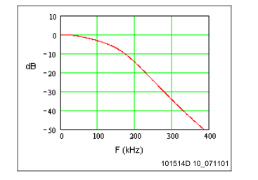
Figure 12. Typical Baseband Frequency Response
Page 45
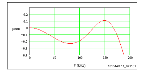
Figure 13. Typical Differential Delay Response
Table 25. EGSM900/GSM850 LNA S11 (Normalized to 50 Ω)
Frequency (MHz)
S11
| 869.0 | 0.386 – 0.632j |
| 878.1 | 0.438 – 0.630j |
| 887.2 | 0.454 – 0.629j |
| 896.3 | 0.420 – 0.639j |
| 905.4 | 0.403 – 0.642j |
| 914.5 | 0.398 – 0.646j |
| 923.6 | 0.371 – 0.653j |
| 932.7 | 0.376 – 0.653j |
| 941.8 | 0.379 – 0.657j |
| 950.9 | 0.343 – 0.664j |
| 960.0 | 0.350 – 0.664j |
Page 46
Table 26. DCS1800 LNA S11 (Normalized to 50 Ω)
Frequency (MHz)
S11
| 1805.0 | 0.0205 – 0.649j |
| 1812.5 | 0.205 – 0.689j |
| 1820.0 | 0.275 – 0.704j |
| 1827.5 | 0.299 – 0.710j |
| 1835.0 | 0.319 – 0.713j |
| 1842.5 | 0.326 – 0.718j |
| 1850.0 | 0.316 – 0.722j |
| 1857.5 | 0.306 – 0.722j |
| 1865.0 | 0.307 – 0.722j |
| 1872.5 | 0.300 – 0.724j |
| 1880.0 | 0.287 – 0.724j |
Table 27. PCS1900 LNA S11 (Normalized to 50 Ω)
Frequency (MHz)
S11
| 1930 | 0.237 – 0.583j |
| 1936 | 0.362 – 0.595j |
| 1942 | 0.432 – 0.591j |
| 1948 | 0.472 – 0.589j |
| 1954 | 0.489 – 0.591j |
| 1960 | 0.488 – 0.597j |
| 1966 | 0.483 – 0.600j |
| 1972 | 0.485 – 0.600j |
| 1978 | 0.484 – 0.600j |
| 1984 | 0.475 – 0.603j |
| 1990 | 0.465 – 0.605j |
Page 47
Table 28. Typical EGSM and GSM850 Band Noise Figure vs. Gain Data
Gain NF Gain NF Gain NF
Gain NF Gain NF Gain NF
| 100.8 | 3.17 | 84.8 | 3.38 | 68.8 | 7.60 | 52.8 | 22.50 | 36.8 | 39.71 | 20.8 | 43.56 |
| 98.8 | 3.17 | 82.8 | 3.48 | 66.8 | 8.39 | 50.8 | 23.76 | 34.8 | 41.11 | 18.8 | 45.01 |
| 96.8 | 3.17 | 80.8 | 3.59 | 64.8 | 11.80 | 48.8 | 24.92 | 32.8 | 42.46 | 16.8 | 46.39 |
| 94.8 | 3.18 | 78.8 | 3.73 | 62.8 | 12.77 | 46.8 | 30.21 | 30.8 | 43.73 | 14.8 | 45.89 |
| 92.8 | 3.20 | 76.8 | 4.90 | 60.8 | 13.71 | 44.8 | 31.29 | 28.8 | 44.89 | 12.8 | 47.58 |
| 90.8 | 3.22 | 74.8 | 5.44 | 58.8 | 18.43 | 42.8 | 32.37 | 26.8 | 42.70 | 10.8 | 49.25 |
| 88.8 | 3.26 | 72.8 | 6.08 | 56.8 | 19.79 | 40.8 | 33.39 | 24.8 | 44.02 | ||
| 86.8 | 3.31 | 70.8 | 6.82 | 54.8 | 21.16 | 38.8 | 38.32 | 22.8 | 45.24 | ||
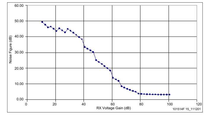
Figure 14. Typical EGSM and GSM850 Band Noise Figure vs. Voltage Gain Curve
(CX74063-26 Only, No Front End Loss)
Page 48
Table 29. Typical EGSM and GSM850 Band Dynamic Range Data (Includes 4.0 dB Front End Loss)
Input Noise P1dB Gain Input Noise
P1dB Gain Input Noise P1dB Gain
Floor
Floor
Floor
| –109.0 | –113.0 | –78.6 | 97.8 | –77.0 | –108.2 | –52.4 | 65.8 | –45.0 | –78.6 | –21.2 | 33.8 |
| –107.0 | –113.0 | –76.6 | 95.8 | –75.0 | –107.1 | –52.0 | 63.8 | –43.0 | –74.5 | –18.1 | 31.8 |
| –105.0 | –113.0 | –74.6 | 93.8 | –73.0 | –106.0 | –51.8 | 61.8 | –41.0 | –72.9 | –17.7 | 29.8 |
| –103.0 | –113.0 | –72.6 | 91.8 | –71.0 | –102.9 | –43.4 | 59.8 | –39.0 | –71.4 | –17.4 | 27.8 |
| –101.0 | –113.0 | –70.6 | 89.8 | –69.0 | –101.6 | –42.5 | 57.8 | –37.0 | –69.8 | –17.2 | 25.8 |
| –99.0 | –113.0 | –68.7 | 87.8 | –67.0 | –100.4 | –41.9 | 55.8 | –35.0 | –68.3 | –17.0 | 23.8 |
| –97.0 | –112.9 | –66.9 | 85.8 | –65.0 | –96.4 | –36.9 | 53.8 | –33.0 | –66.9 | –17.0 | 21.8 |
| –95.0 | –112.9 | –65.2 | 83.8 | –63.0 | –94.9 | –35.9 | 51.8 | –31.0 | –66.9 | –16.9 | 19.8 |
| –93.0 | –112.8 | –63.7 | 81.8 | –61.0 | –93.4 | –35.2 | 49.8 | –29.0 | –65.2 | –16.9 | 17.8 |
| –91.0 | –112.7 | –62.4 | 79.8 | –59.0 | –91.8 | –34.6 | 47.8 | –27.0 | –63.4 | –16.9 | 15.8 |
| –89.0 | –112.5 | –61.4 | 77.8 | –57.0 | –90.3 | –34.3 | 45.8 | –25.0 | –62.3 | –16.8 | 13.8 |
| –87.0 | –112.3 | –60.5 | 75.8 | –55.0 | –88.9 | –34.0 | 43.8 | –23.0 | –60.3 | –16.8 | 11.8 |
| –85.0 | –112.1 | –59.9 | 73.8 | –53.0 | –83.8 | –24.3 | 41.8 | –21.0 | –58.4 | –16.8 | 9.8 |
| –83.0 | –110.8 | –54.8 | 71.8 | –51.0 | –82.6 | –23.2 | 39.8 | –19.0 | –56.7 | –16.8 | 7.8 |
| –81.0 | –110.0 | –53.8 | 69.8 | –49.0 | –81.3 | –22.3 | 37.8 | –17.0 | –54.7 | –16.8 | 5.8 |
| –79.0 | –109.2 | –53.0 | 67.8 | –47.0 | –79.9 | –21.7 | 35.8 | –15.0 | –52.7 | –16.8 | 3.8 |
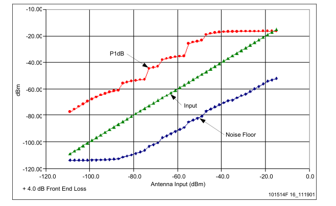
Figure 15. Typical EGSM and GSM850 Band Dynamic Range vs. Antenna Input Curve
Page 49
Table 30. Typical DCS1800 Band Noise Figure vs. Gain Data
Gain
NF
Gain
NF
Gain
NF
Gain
NF
Gain
NF
Gain
NF
| 100 | 3.7 | 84 | 3.9 | 68 | 8.3 | 52 | 23.3 | 36 | 41.1 | 20 | 48.0 |
| 98 | 3.7 | 82 | 4.0 | 66 | 9.1 | 50 | 24.6 | 34 | 42.5 | 18 | 46.4 |
| 96 | 3.7 | 80 | 4.1 | 64 | 12.6 | 48 | 25.7 | 32 | 43.9 | 16 | 47.8 |
| 94 | 3.7 | 78 | 4.3 | 62 | 13.6 | 46 | 32.0 | 30 | 45.3 | 14 | 49.2 |
| 92 | 3.7 | 76 | 5.5 | 60 | 14.5 | 44 | 33.0 | 28 | 46.5 | 12 | 48.7 |
| 90 | 3.7 | 74 | 6.1 | 58 | 19.2 | 42 | 34.1 | 26 | 47.7 | 10 | 50.4 |
| 88 | 3.8 | 72 | 6.7 | 56 | 20.6 | 40 | 35.2 | 24 | 45.5 | ||
| 86 | 3.8 | 70 | 7.5 | 54 | 22.0 | 38 | 36.2 | 22 | 46.8 | ||
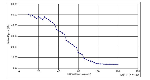
Figure 16. Typical DCS1800 Band Noise Figure vs. Voltage Gain Curve
(CX74063-26 Only; No Front End Loss)
Page 50
Table 31. Typical DCS1800 Band Dynamic Range Data (Includes 4.2 dB Front End Loss)
Input Noise P1dB Gain Input Noise
P1dB Gain Input Noise P1dB Gain
Floor
Floor
Floor
| –109.0 | –113.0 | –78.6 | 97.8 | –77.0 | –108.2 | –52.4 | 65.8 | –45.0 | –78.6 | –21.2 | 33.8 |
| –107.0 | –113.0 | –76.6 | 95.8 | –75.0 | –107.1 | –52.0 | 63.8 | –43.0 | –74.5 | –18.1 | 31.8 |
| –105.0 | –113.0 | –74.6 | 93.8 | –73.0 | –106.0 | –51.8 | 61.8 | –41.0 | –72.9 | –17.7 | 29.8 |
| –103.0 | –113.0 | –72.6 | 91.8 | –71.0 | –102.9 | –43.4 | 59.8 | –39.0 | –71.4 | –17.4 | 27.8 |
| –101.0 | –113.0 | –70.6 | 89.8 | –69.0 | –101.6 | –42.5 | 57.8 | –37.0 | –69.8 | –17.2 | 25.8 |
| –99.0 | –113.0 | –68.7 | 87.8 | –67.0 | –100.4 | –41.9 | 55.8 | –35.0 | –68.3 | –17.0 | 23.8 |
| –97.0 | –112.9 | –66.9 | 85.8 | –65.0 | –96.4 | –36.9 | 53.8 | –33.0 | –66.9 | –17.0 | 21.8 |
| –95.0 | –112.9 | –65.2 | 83.8 | –63.0 | –94.9 | –35.9 | 51.8 | –31.0 | –66.9 | –16.9 | 19.8 |
| –93.0 | –112.8 | –63.7 | 81.8 | –61.0 | –93.4 | –35.2 | 49.8 | –29.0 | –65.2 | –16.9 | 17.8 |
| –91.0 | –112.7 | –62.4 | 79.8 | –59.0 | –91.8 | –34.6 | 47.8 | –27.0 | –63.4 | –16.9 | 15.8 |
| –89.0 | –112.5 | –61.4 | 77.8 | –57.0 | –90.3 | –34.3 | 45.8 | –25.0 | –62.3 | –16.8 | 13.8 |
| –87.0 | –112.3 | –60.5 | 75.8 | –55.0 | –88.9 | –34.0 | 43.8 | –23.0 | –60.3 | –16.8 | 11.8 |
| –85.0 | –112.1 | –59.9 | 73.8 | –53.0 | –83.8 | –24.3 | 41.8 | –21.0 | –58.4 | –16.8 | 9.8 |
| –83.0 | –110.8 | –54.8 | 71.8 | –51.0 | –82.6 | –23.2 | 39.8 | –19.0 | –56.7 | –16.8 | 7.8 |
| –81.0 | –110.0 | –53.8 | 69.8 | –49.0 | –81.3 | –22.3 | 37.8 | –17.0 | –54.7 | –16.8 | 5.8 |
| –79.0 | –109.2 | –53.0 | 67.8 | –47.0 | –79.9 | –21.7 | 35.8 | –15.0 | –52.7 | –16.8 | 3.8 |
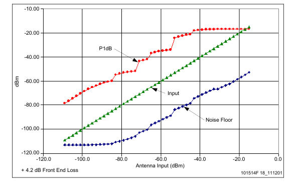
Figure 17. Typical DCS1800 Band Dynamic Range vs. Antenna Input Curve
Page 51
Table 32. Typical PCS1900 Band Noise Figure vs. Gain Data
Gain NF Gain NF Gain NF
Gain NF Gain NF Gain NF
| 98.8 | 4.2 | 82.8 | 4.5 | 66.8 | 9.3 | 50.8 | 24.5 | 34.8 | 42.3 | 18.8 | 49.2 |
| 96.8 | 4.2 | 80.8 | 4.6 | 64.8 | 10.1 | 48.8 | 25.8 | 32.8 | 43.7 | 16.8 | 47.6 |
| 94.8 | 4.2 | 78.8 | 4.7 | 62.8 | 13.7 | 46.8 | 26.9 | 30.8 | 45.1 | 14.8 | 49.0 |
| 92.8 | 4.2 | 76.8 | 4.9 | 60.8 | 14.7 | 44.8 | 33.2 | 28.8 | 46.5 | 12.8 | 50.4 |
| 90.8 | 4.2 | 74.8 | 6.3 | 58.8 | 15.6 | 42.8 | 34.2 | 26.8 | 47.7 | 10.8 | 49.9 |
| 88.8 | 4.3 | 72.8 | 6.9 | 56.8 | 20.4 | 40.8 | 35.3 | 24.8 | 48.9 | 8.8 | 51.6 |
| 86.8 | 4.3 | 70.8 | 7.6 | 54.8 | 21.8 | 38.8 | 36.4 | 22.8 | 46.7 | 6.8 | 53.3 |
| 84.8 | 4.4 | 68.8 | 8.4 | 52.8 | 23.1 | 36.8 | 37.4 | 20.8 | 48.0 | ||
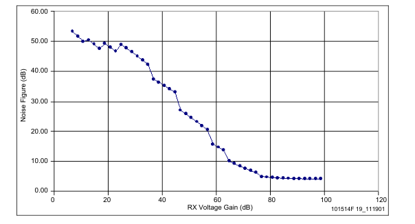
Figure 18. Typical PCS1900 Band Noise Figure vs. Voltage Gain Curve
(CX74063-26 Only; No Front End Loss)
Page 52
Table 33. Typical PCS1900 Band Dynamic Range Data (Includes 4.2 dB Front End Loss)
Input Noise P1dB Gain Input Noise
P1dB Gain Input Noise P1dB Gain
Floor
Floor
Floor
| –109.0 | –112.5 | –77.4 | 96.6 | –77.0 | –107.4 | –51.2 | 64.6 | –45.0 | –77.7 | –20.3 | 32.6 |
| –107.0 | –112.5 | –75.4 | 94.6 | –75.0 | –106.3 | –50.8 | 62.6 | –43.0 | –73.5 | –17.6 | 30.6 |
| –105.0 | –112.5 | –73.4 | 92.6 | –73.0 | –105.2 | –50.6 | 60.6 | –41.0 | –72.0 | –17.2 | 28.6 |
| –103.0 | –112.5 | –71.4 | 90.6 | –71.0 | –102.0 | –42.2 | 58.6 | –39.0 | –70.4 | –17.0 | 26.6 |
| –101.0 | –112.5 | –69.4 | 88.6 | –69.0 | –100.7 | –41.3 | 56.6 | –37.0 | –68.9 | –16.8 | 24.6 |
| –99.0 | –112.5 | –67.5 | 86.6 | –67.0 | –99.5 | –40.7 | 54.6 | –35.0 | –67.4 | –16.7 | 22.6 |
| –97.0 | –112.4 | –65.7 | 84.6 | –65.0 | –95.4 | –35.7 | 52.6 | –33.0 | –66.0 | –16.6 | 20.6 |
| –95.0 | –112.4 | –64.0 | 82.6 | –63.0 | –93.9 | –34.7 | 50.6 | –31.0 | –66.3 | –16.6 | 18.6 |
| –93.0 | –112.3 | –62.5 | 80.6 | –61.0 | –92.4 | –34.0 | 48.6 | –29.0 | –64.6 | –16.5 | 16.6 |
| –91.0 | –112.1 | –61.2 | 78.6 | –59.0 | –90.9 | –33.4 | 46.6 | –27.0 | –62.9 | –16.5 | 14.6 |
| –89.0 | –112.0 | –60.2 | 76.6 | –57.0 | –89.4 | –33.1 | 44.6 | –25.0 | –61.8 | –16.5 | 12.6 |
| –87.0 | –111.8 | –59.3 | 74.6 | –55.0 | –88.0 | –32.8 | 42.6 | –23.0 | –59.9 | –16.5 | 10.6 |
| –85.0 | –111.5 | –58.7 | 72.6 | –53.0 | –82.8 | –23.3 | 40.6 | –21.0 | –58.0 | –16.5 | 8.6 |
| –83.0 | –110.0 | –53.6 | 70.6 | –51.0 | –81.6 | –22.2 | 38.6 | –19.0 | –56.3 | –16.5 | 6.6 |
| –81.0 | –109.3 | –52.6 | 68.6 | –49.0 | –80.3 | –21.4 | 36.6 | –17.0 | –54.3 | –16.5 | 4.6 |
| –79.0 | –108.4 | –51.8 | 66.6 | –47.0 | –79.0 | –20.8 | 34.6 | –15.0 | –52.4 | –16.5 | 2.6 |
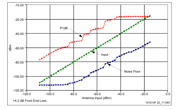
Figure 19. Typical PCS1900 Band Dynamic Range vs. Antenna Input Curve
Page 53
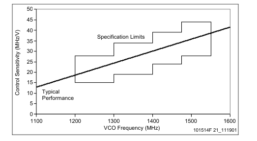
Figure 20. Typical Control Sensitivity, UHF VCO
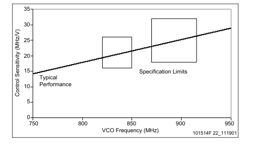
Figure 21. Typical Control Sensitivity, Low Band TX VCO
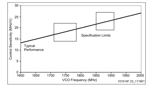
Figure 22. Typical Control Sensitivity, High Band TX VCO
Page 54
Transmitter Data
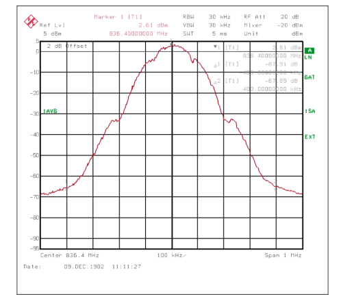
Figure 23. Typical GSM850 Band Output Spectrum
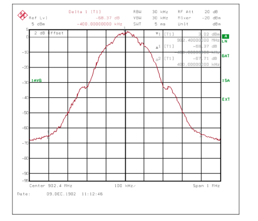
Figure 24. Typical EGSM Band Output Spectrum
Page 55
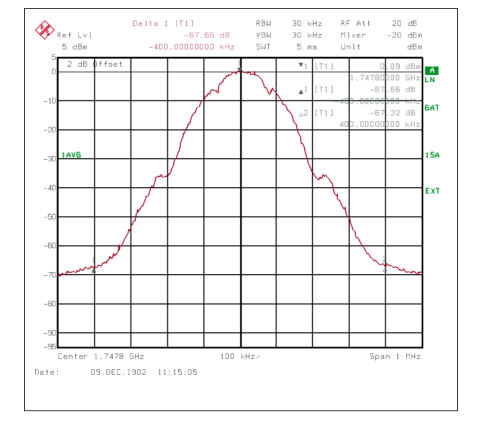
Figure 25. Typical DCS Band Output Spectrum
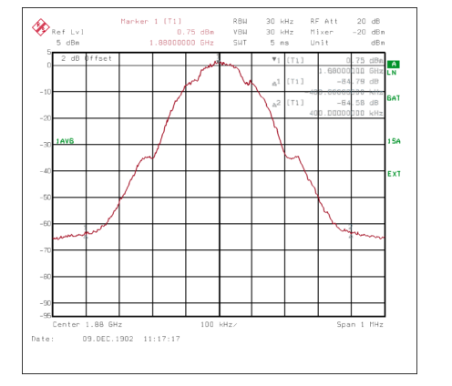
Figure 26. Typical PCS Band Output Spectrum
Page 56
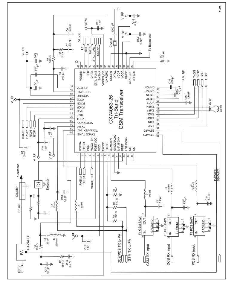
Figure 27. Typical CX74063-26 Application Circuit
Page 57
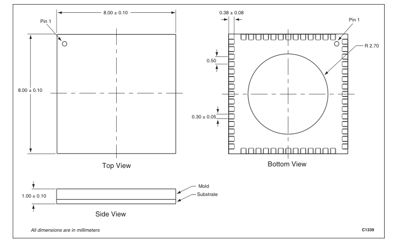
Figure 28. CX74063-26 56-Pin RFLGA Package Dimension Drawing
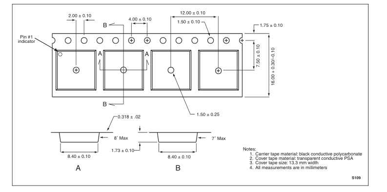
Figure 29. CX74063-26 56-Pin RFLGA Tape and Reel Dimensions
Page 58
Ordering Information
Manufacturing Part Number
Model Name
Product Revision
CX74063
CX74063-26
© 2001, 2002, 2003 Skyworks Solutions, Inc. All Rights Reserved.
Information in this document is provided in connection with Skyworks Solutions, Inc. ("Skyworks") products. These materials are provided by Skyworks as a service to its customers and may be used for informational purposes only. Skyworks assumes no responsibility for errors or omissions in these materials. Skyworks may make changes to its products, specifications and product descriptions at any time, without notice. Skyworks makes no commitment to update the information and shall have no responsibility whatsoever for conflicts, incompatibilities, or other difficulties arising from future changes to its products and product descriptions.
No license, express or implied, by estoppel or otherwise, to any intellectual property rights is granted by this document. Except as may be provided in Skyworks’ Terms and Conditions of Sale for such products, Skyworks assumes no liability whatsoever.
THESE MATERIALS ARE PROVIDED "AS IS" WITHOUT WARRANTY OF ANY KIND, EITHER EXPRESS OR IMPLIED, RELATING TO SALE AND/OR USE OF SKYWORKS™ PRODUCTS INCLUDING WARRANTIES RELATING TO FITNESS FOR A PARTICULAR PURPOSE, MERCHANTABILITY, PERFORMANCE, QUALITY OR NON-INFRINGEMENT OF ANY PATENT, COPYRIGHT OR OTHER INTELLECTUAL PROPERTY RIGHT. SKYWORKS FURTHER DOES NOT WARRANT THE ACCURACY OR COMPLETENESS OF THE INFORMATION, TEXT, GRAPHICS OR OTHER ITEMS CONTAINED WITHIN THESE MATERIALS. SKYWORKS SHALL NOT BE LIABLE FOR ANY SPECIAL, INDIRECT, INCIDENTAL, OR CONSEQUENTIAL DAMAGES, INCLUDING WITHOUT LIMITATION, LOST REVENUES OR LOST PROFITS THAT MAY RESULT FROM THE USE OF THESE MATERIALS.
Skyworks™ products are not intended for use in medical, lifesaving or life-sustaining applications. Skyworks’ customers using or selling Skyworks™ products for use in such applications do so at their own risk and agree to fully indemnify Skyworks for any damages resulting from such improper use or sale.
The following are trademarks of Skyworks Solutions, Inc.: Skyworks™, the Skyworks symbol, “Single Package Radio”™, SPR™, and “Breakthrough Simplicity”™. Product names or services listed in this publication are for identification purposes only, and may be trademarks of third parties. Third-party brands and names are the property of their respective owners.
GSM™, “Global System for Mobile Communications™,” and the GSM logo are trademarks of the GSM Association. RFLGA™ is a trademark of Conexant Systems, Inc.
Additional information, posted at www.skyworksinc.com, is incorporated by reference.
Page 59