


 Download PDF
CX74001 SKYWORKS
Document overview
- PDF pages: 23
Technical content
Page 1
The CX74001 Application-Specific Integrated Circuit (ASIC) is a triple-mode, dualband receiver (Rx) intended for use in Code Division Multiple Access (CDMA) portable phones in both cellular and Personal Communications System (PCS) bands, as well as Advanced Mobile Phone System (AMPS) mode.
The device is a highly integrated super-heterodyne receiver. It incorporates all the components required to implement the receiver chain, from the low-noise amplifier (LNA) to the In-Phase and Quadrature (I/Q) demodulator stages, except for the external Surface Acoustic Wave (SAW) filters and matching components. There are two internal Low Noise Amplifiers (LNAs). The Cellular LNA has three-step gain stages, and the PCS LNA gain has a bypass feature.
After RF signal amplification and filtering, the received signal is mixed down from RF to the Intermediate Frequency (IF). There are separate mixers for AMPS, CDMA, and PCS bands. The CDMA cellular and PCS mixers have balanced outputs for the IF SAW filters, while the AMPS differential output can be combined externally to mate to a single-ended SAW filter. After IF filtering, the IF signal is amplified by a Variable Gain Amplifier (VGA) and fed to an I/Q demodulator resulting in baseband I/Q signals at the output.
The VGA has a minimum dynamic range of 90 dB with a control voltage range from 0.5 to 2.5 Volts, and it is common to all modes. There are two VHF oscillators which operates with external tank circuits to provide Local Oscillator (LO) frequencies for the I/Q demodulator in the cellular and PCS bands.
The noise figure, gain, and third order Input Intercept Point (IIP3) of each stage in the receiver chip are optimized to meet the system requirements for AMPS and CDMA modes as per TIA/EIA-98-C. Employing BiCMOS technology, the ASIC is designed for low cost, high performance, and a high level of integration.
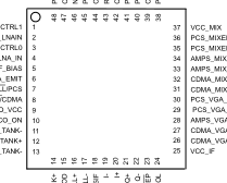
The device package and pinout are shown in Figure 1. A system block diagram of the CX74001 is shown in Figure 2.
Data Sheet

Distinguishing Features
- Supports single and dual-band, and tri-mode handsets
- Battery cell operation (2.7 V < Vcc < 3.3 V)
- Dual Low Noise Amplifiers (800 MHz / 1900 MHz)
- PCS LNA With Bypass Feature
- Three-Step Cellular LNA Gain
- I/Q Interface
- Dual 200-600 MHz VHF Oscillators
- VCO On/Off control For Standby Current Optimization
- CDMA Single IF Feature
- 48-pin, 7 x 7 mm RF Land Grid Array (RFLGA™) package with down-set paddle.
Applications
- Cellular and PCS band phones
- CDMA and AMPS modes in the cellular band
- AMPS
- CDMA-US
- CDMA-Japan
- CDMA mode in the PCS band
- PCS-US
- PCS-Korea
LNA_CTRL1 PCS_LNAIN
PCS_MIXER_OUT+
LNA_CTRL0
PCS_MIXER_OUT-
CELL_LNA_IN
AMPS_MIX_OUT+
VCC_RF_BIAS
AMPS_MIX_OUT-
CELL_LNA_EMIT
CDMA_MIX_OUT+
CELL/PCS
CDMA_MIX_OUT-
VCO_VCC
CELL_TANK- CELL_TANK+ PCS_TANK-
CNXT061
Figure 1. CX74001 Rx ASIC Pin-Out (Top View)
Doc. No. 101134A
Page 2
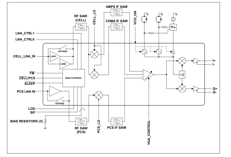
Figure 2. CX74001 Rx ASIC Block Diagram
Technical Description
Low Noise Amplifiers (LNAs) _________________________
The cellular band LNA is designed with a low noise figure and high linearity to achieve receiver sensitivity and single-tone requirements. The cellular LNA is a three-step gain LNA designed to meet the inter-modulation distortion specifications in CDMA per TIA/EIA 98-C.
The PCS band LNA is also designed to provide a low noise figure and high linearity to achieve receiver sensitivity and single-tone requirements. At high signal strength, it is preferable to bypass the LNA completely, and the PCS LNA supports this feature.
Mixers ____________________________________________
The CX74001 Rx ASIC has three independent mixers, one for the PCS band and two for the cellular band (AMPS and CDMA). The mixers are designed to operate with LO powers of –10 dBm, typical.
The cellular and PCS band mixers have a high gain and IIP3, and a low noise figure that allow them to meet the system
requirements with margin. The cellular CDMA and PCS mixers have balanced output to drive the IF SAW filters. The differential outputs of the AMPS mixer are combined externally to mate to a single-ended input IF SAW filter.
Variable Gain Amplifier (VGA) _________________________
The high dynamic range required by CDMA handsets is achieved by the VGA, which is common to all modes. It has three different inputs and the appropriate signal path is switched inside the chip. The VGA has a dynamic range of 90 dB with a control voltage of 0.5 to 2.5 volts. It has a low noise figure at maximum gain, which allows it to meet the system noise figure requirements. The balanced output is common for all the modes and is fed directly to the I/Q Demodulator.
I/Q Demodulator_____________________________________
The VGA stage is internally AC coupled to the I/Q demodulator. The LO signals are derived from one of the on-chip VCOs, then fed to a divider block that divides the VCO frequency by two. The differential I and Q outputs are designed specifically with a low DC output offset and a low phase and amplitude imbalance when cascaded with the baseband processor.
Page 3
Voltage Controlled Oscillators (VCOs)__________________
The active cores of the two VCOs are present on the CX74001, requiring only differential external LC tanks and a PLL synthesizer. The VCO core current is automatically adjusted to give a constant VCO output swing, regardless of the external tank Q.
Mode Control ______________________________________
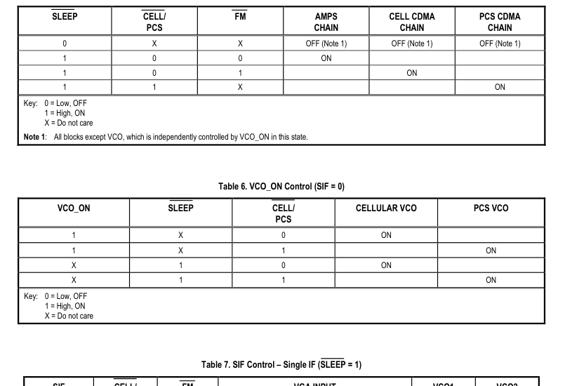
The operation of the chip is controlled by signals CELL/PCS, FM, and SLEEP. The Single IF (SIF) is added to use a common IF frequency for CDMA mode in cellular and PCS band. This allows the use of one IF SAW filter for the PCS and CDMA modes to reduce system implementation cost. The logic blocks are powered off of the Vcc_IF, so it must be present to obtain chip functionality.
Electrical and Mechanical Specifications.
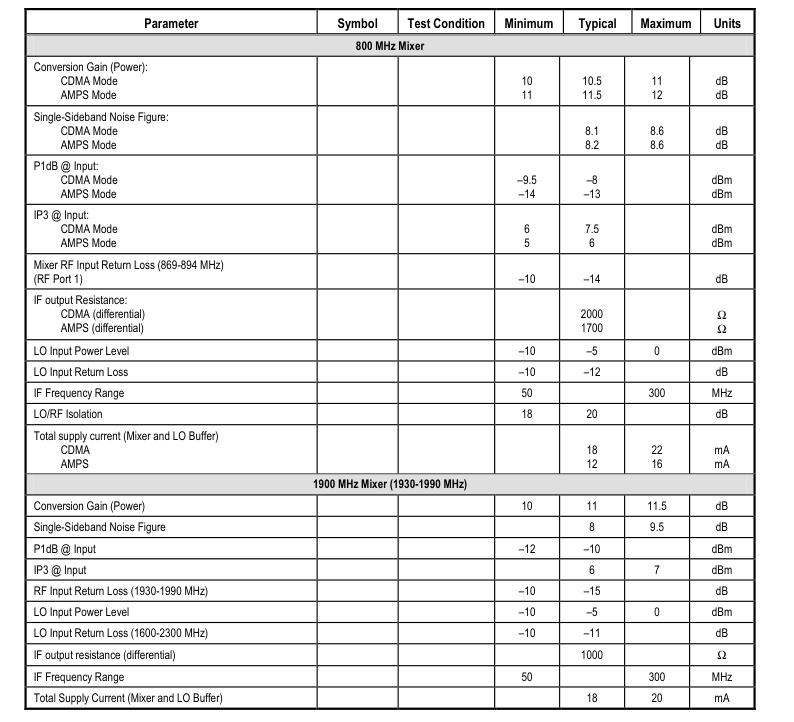
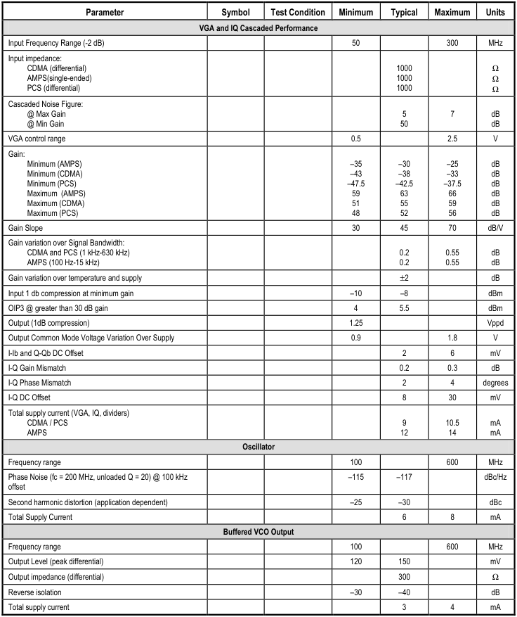
Signal pin assignments and functional pin descriptions are described in Table 1. The absolute maximum ratings of the CX74001 are provided in Table 2. The recommended operating conditions are specified in Table 3. Electrical specifications are
provided in Table 4. Tables 5, 6, 7, and 8 provide logic and mode control information for the CX74001.
Figures 3 through 46 provide typical performance characteristics. A schematic diagram of the CX74001 is provided in Figure 47 and the package dimensions of the 48-pin RFLGA are shown in Figure 48.
ESD Sensitivity
The CX74001 is a JEDEC Class 1 device. The following extreme Electrostatic Discharge (ESD) precautions are required according to the Human Body Model (HBM):
- Protective outer garments.
- Handle device in ESD safeguarded work area.
- Transport device in ESD shielded containers.
- Monitor and test all ESD protection equipment.
The HBM ESD withstand threshold value, with respect to ground, is ±1.5 kV. The HBM ESD withstand threshold value, with respect to VDD (the positive power supply terminal) is also ±1.5 kV.
Page 4
Table 1. CX74001 Pin Assignments and Signal Descriptions (1 of 4)
| Pin # | Name | Description | Equivalent Circuit |
|---|---|---|---|
| 1 | LNA_CTRL1 | Digital signal used in conjunction with pin 3 to control LNA gain step. DO NOT ALLOW TO FLOAT OR LEAVE UNCONNECTED | Vcc |
| 2 | PCS_LNAIN | PCS LNA input pin. High-Q matching network should be used to minimize noise figure, and a DC blocking capacitor is required. | |
| 3 | LNA_CTRL0 | Digital signal used in conjunction with pin 1 to control LNA gain step. DO NOT ALLOW TO FLOAT OR LEAVE UNCONNECTED | Vcc |
| 4 | CELL_LNA_IN | Cellular LNA input pin. High-Q matching network should be used to minimize noise figure, and a DC blocking capacitor is required. | |
| 5 | VCC_RF_BIAS | Supply voltage to the RF bias (needed by all LNA/Mixer blocks) . An RF bypass capacitor should be connected from the pin to ground with minimal trace length. | |
| 6 | CELL_LNA_EMIT | Ground directly to ground with minimum trace length. | |
| 7 | CELL/PCS | Digital signal used for band selection: 0 = cellular (800 MHz), 1 = PCS (1900 MHz). | |
| 8 | FM/CDMA | Digital signal used in cellular band for mode selection: 0 = AMPS, 1 = CDMA. | |
| 9 | VCO_VCC | Voltage supply to the VCO buffers. A bypass capacitor should be placed close to the device from pin 9 to ground with minimal trace length. | |
| 10 | VCO_ON | VCO control signal to turn VCO and PLL buffer ON/OFF during slotted paging modes, thereby increasing standby time. | |
| 11 | CELL_TANK– | Differential tank cellular band VCO pin. Care should be taken during the layout of the external tank circuit to prevent parasitic oscillations. | – + |
| 12 | CELL_TANK+ | Differential tank cellular band VCO pin. Care should be taken during the layout of the external tank circuit to prevent parasitic oscillations. | |
| 13 | PCS_TANK– | Differential tank PCS band VCO pin. Care should be taken during the layout of the external tank circuit to prevent parasitic oscillations. | |
| 14 | PCS_TANK+ | Differential tank PCS band VCO pin. Care should be taken during the layout of the external tank circuit to prevent parasitic oscillations. | |
| 15 | LOD | Linearity On Demand. It provides the bias control for the mixers, thereby reducing the chip current consumption at the expense of input IP3. |
Page 5
Table 1. CX74001 Pin Assignments and Signal Descriptions (2 of 4)
| Pin # | Name | Description | Equivalent Circuit |
|---|---|---|---|
| 16 | PLL+ | Differential buffered VCO output. | Vcc Vcc – + |
| 17 | PLL– | Differential buffered VCO output. | |
| 18 | SIF | Digital control signal for SIF selection: 1 = SIF, 0 = Normal. | |
| 19 | I– | I channel differential output. | |
| 20 | I+ | I channel differential output. | |
| 21 | Q+ | Q channel differential output. | |
| 22 | Q– | Q channel differential output. | |
| 23 | SLEEP | Digital signal used to activate the receiver ASIC: 0 = sleep, 1= enable. | |
| 24 | VGA_CONTROL | Analog gain control of the VGA. Typical 0.5 to 2.5 V to control VGA dynamic range of greater than 90dB. | |
| 25 | VCC_IF | Voltage supply to VGA from I/Q demodulator stages and logic blocks. Supply should be bypassed to prevent signal modulation to the supply line. | |
| 26 | CDMA_VGA_IN– | CDMA differential VGA input | + – |
| 27 | CDMA_VGA_IN+ | CDMA differential VGA input | |
| 28 | AMPS_VGA_IN | AMPS VGA input | |
| 29 | PCS_VGA_IN– | PCS differential VGA input | + – |
| 30 | PCS_VGA_IN+ | PCS differential VGA input |
Page 6
Table 1. CX74001 Pin Assignments and Signal Descriptions (3 of 4)
| Pin # | Name | Description | Equivalent Circuit |
|---|---|---|---|
| 31 | CDMA_MIX_OUT– | CDMA differential cellular mixer open collector output. VCC pull up inductor is required, and the output impedance is set by an external matching network. | + – |
| 32 | CDMA_MIX_OUT+ | CDMA differential cellular mixer open collector output. VCC pull up inductor is required, and the output impedance is set by an external matching network. | |
| 33 | AMPS_MIX_OUT– | AMPS differential mixer open collector output. VCC pull up inductor is required, and the output impedance is set by an external matching network. | |
| 34 | AMPS_MIX_OUT+ | AMPS differential mixer open collector output. VCC pull up inductor is required, and the output impedance is set by an external matching network. | |
| 35 | PCS_MIXER_OUT– | PCS differential mixer open collector output. VCC pull up inductor is required, and the output impedance is set by an external matching network. | |
| 36 | PCS_MIXER_OUT+ | PCS differential mixer open collector output. VCC pull up inductor is required, and the output impedance is set by an external matching network. | |
| 37 | VCC_MIX | Voltage supply for the mixers. RF bypass capacitor should be close to pin with minimal trace length. | |
| 38 | PCS_LO | The local oscillator input for the PCS band mixer. | |
| 39 | CELL_LO | The local oscillator input for the cellular band mixer. | |
| 40 | PCSMIX_BYPASS | Low frequency bypass for the PCS mixer. Typically, a 47 nF is connected from pin to ground. | |
| 41 | PCS_MIX_IN | PCS mixer input. Requires AC coupling capacitor | |
| 42 | CELL_MIX_IN | Cellular mixer input | |
| 43 | RF_BIAS_RES | This sets the RF bias current. Typically, a 15 kΩ resistor is connected from the pin to ground. | |
| 44 | CELL_LNA_BIAS_RES | This sets the cellular LNA bias current. Typically, 27 kΩ is connected to ground. |
Page 7
Table 1. CX74001 Pin Assignments and Signal Descriptions (4 of 4)
| Pin # | Name | Description | Equivalent Circuit |
|---|---|---|---|
| 45 | PCS_LNA_OUT | PCS LNA open collector output. VCC inductor pull up and external matching network are required. | |
| 46 | NC | No Connection. | |
| 47 | CELL_LNA_OUT | Cellular LNA open collector output. VCC inductor pull up and external matching network are required. | |
| 48 | PCS_LNA_BIAS_RES | This set the PCS LNA bias current. Typically, a 220 Ω resistor is connected from the pin to ground. |
Table 2. Absolute Maximum Ratings
| Parameter | Minimum | Maximum | Units |
|---|---|---|---|
| Supply voltage (VCC) | –0.3 | +5.5 | V |
| Input voltage range | –0.3 | VCC | V |
| LNA input power | +5 | dBm | |
| Power dissipation | 600 | mW | |
| Ambient operating temperature | –30 | +80 | °C |
| Storage temperature | –40 | +125 | °C |
Table 3. Recommended Operating Conditions
| Parameter | Minimum | Typical | Maximum | Units |
|---|---|---|---|---|
| Supply voltage (VCC) | 2.7 | 3.0 | 3.3 | V |
| Operating temperature | –30 | +25 | +80 | °C |
| Impedance of logic inputs | 50 | kΩ | ||
| VIL Logic Low Input Voltage | 0.0 | 0.5 | V | |
| VIH Logic High Input Voltage | VCC – 0.5 | VCC | V |
Page 8
Table 4. CX74001 Rx ASIC Electrical Specifications (1 of 3)
(TA = 25°°°° C, VCC = 3.0 V)
| Parameter | Symbol | Test Condition | Minimum | Typical | Maximum | Units |
|---|---|---|---|---|---|---|
| 800 MHz LNA CDMA | ||||||
| High Gain | 15.5 | 16 | 16.5 | dB | ||
| Medium Gain | 6 | 6.4 | 7 | dB | ||
| Low Gain | –3 | –5 | –6 | dB | ||
| Noise Figure @ High Gain | 1.6 | 1.8 | dB | |||
| Noise Figure @ Medium Gain | 2.8 | 4 | dB | |||
| Noise Figure @ Low Gain | 5 | 6.4 | dB | |||
| Input IP3 @ High Gain | 5 | 6 | dBm | |||
| Input IP3 @ Medium Gain | 10 | 15 | dBm | |||
| Input IP3 @ Low Gain | 20 | 22 | dBm | |||
| Reverse isolation | 18 | 20 | dB | |||
| Input return loss (869-894 MHz) | –10 | –15 | dB | |||
| Output return loss (869-894 MHz) | –10 | –12 | dB | |||
| Total supply current (adjustable) | 8 | 8.5 | mA | |||
| 800 MHz LNA AMPS | ||||||
| Gain @ 881 MHz | 15 | 15.5 | 16 | dB | ||
| Noise Figure | 1.4 | 1.6 | dB | |||
| Input IP3 | –2 | 0 | dBm | |||
| Reverse Isolation | 19 | 20 | dB | |||
| Input return loss | –10 | –15 | dB | |||
| Output return loss | –10 | –15 | dB | |||
| Total supply current | 4.5 | 5 | mA | |||
| 1900 MHz LNA | ||||||
| Gain 1 (High) | 15 | 15.5 | 16 | dB | ||
| Gain 2 (LNA Bypass) | –5 | –4 | –3 | dB | ||
| Noise Figure 1 (High) | 1.8 | 2 | dB | |||
| Noise Figure 2 (LNA Bypass) | 4 | 5 | dB | |||
| Input IP3 1 (High Gain) | 2 | 3 | dBm | |||
| Input IP3 (LNA Bypass) | 20 | 21 | dBm | |||
| Reverse Isolation | 19 | 20 | dB | |||
| Input return loss (1930-1990 MHz) | –8 | –12 | dB | |||
| Output return loss (1930-1990 MHz) | –10 | –12 | dB | |||
| Total supply current (Adjustable) | 7.5 | 10 | mA | |||
Page 9
Table 4. CX74001 Rx ASIC Electrical Specifications (2 of 3)
(TA = 25°°°° C, VCC = 3.0 V)
Page 10
Table 4. CX74001 Rx ASIC Electrical Specifications (3 of 3)
(TA = 25°°°° C, VCC = 3.0 V)
Page 11
Table 5. Mode Control Select Signal Switching
| SIF | CELL/ PCS | FM | VGA INPUT | VCO1 CELL | VCO2 PCS | ||
| AMPS | CDMA | PCS | |||||
| 0 | 0 | 0 | ON | ON | |||
| 0 | 0 | 1 | ON | ON | |||
| 0 | 1 | X | ON | ON | |||
| 1 | 0 | 0 | ON | ON | |||
| 1 | 0 | 1 | ON | ON | |||
| 1 | 1 | X | ON | ON | |||
| Key: 0 = Low, OFF 1 = High, ON X = Do not care | |||||||
Page 12
Table 8. Logic Control for LNA Gain Step
| LNA_CTRL0 | LNA_CTRL1 | AMPS | CELL CDMA | PCS CDMA |
| 0 | 0 | HIGH | HIGH | HIGH |
| 1 | 0 | MEDIUM (Note 1) | MEDIUM | BYPASS |
| 0 | 1 | BYPASS (Note 1) | BYPASS | HIGH |
| 1 | 1 | BYPASS (Note 1) | BYPASS | BYPASS |
| Key: 0 = Low, OFF 1 = High, ON X = Do not care Note 1: These modes are available but not used to meet the IS-98 Specifications. | ||||
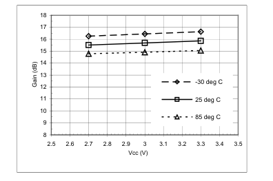
Figure 3. PCS LNA Gain at 1960 MHz
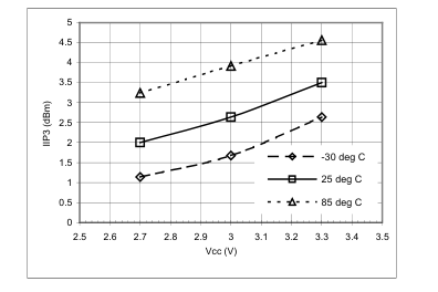
Figure 5. PCS LNA IIP3 at 1960 MHz
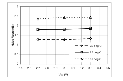
Figure 4. PCS LNA NF at 1960 MHz
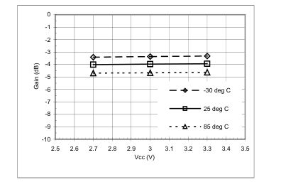
Figure 6. PCS LNA Gain at 1960 MHz(Bypass Mode)
Page 13
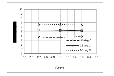
Figure 7. PCS LNA NF (Bypass Mode)
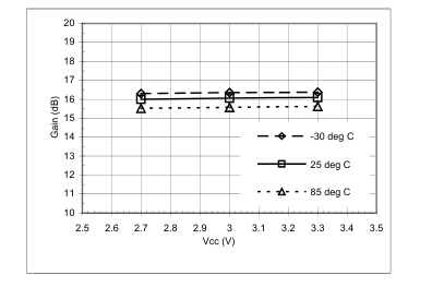
Figure 9. Cell CDMA LNA GAIN at 881 MHz
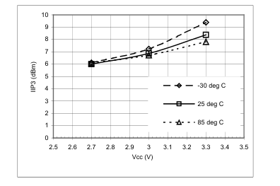
Figure 11. Cell CDMA LNA IIP3 (High Gain) at 881 MHz
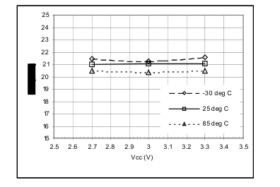
Figure 8. PCS LNA IIP3 (Bypass Mode)
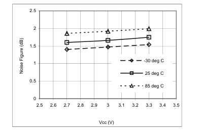
Figure 10. Cell CDMA LNA NF at 881 MHz
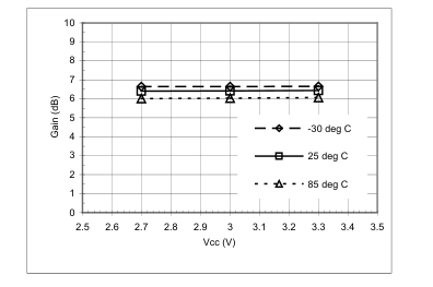
Figure 12. Cell CDMA LNA Gain (Mid Gain) at 881 MHz
Page 14
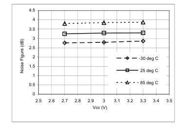
Figure 13. Cell CDMA LNA Noise Figure (Mid Gain) at 881 MHz
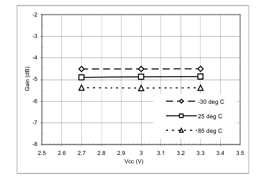
Figure 15. Cell CDMA LNA Gain (Bypass Mode) at 881 MHz
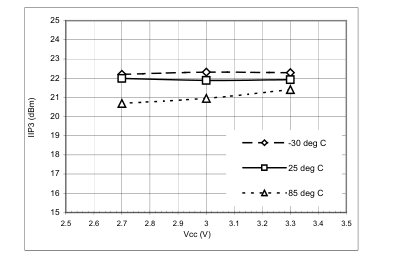
Figure 17 Cell CDMA LNA IIP3 (Bypass Mode) at 881 MHz
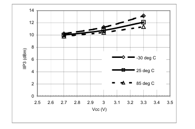
Figure 14. Cell CDMA LNA IIP3 (Mid Gain) at 881 MHz
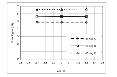
Figure 16. Cell CDMA LNA Noise Figure (Bypass Mode) at 881 MHz
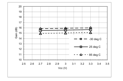
Figure 18. AMPS LNA Gain at 881 MHz
Page 15
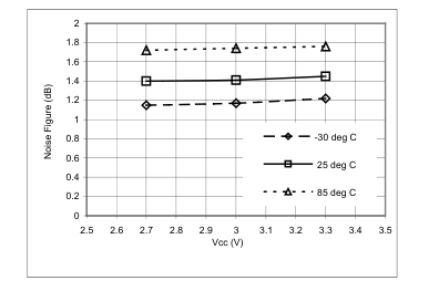
Figure 19. AMPS LNA Noise Figure at 881 MHz
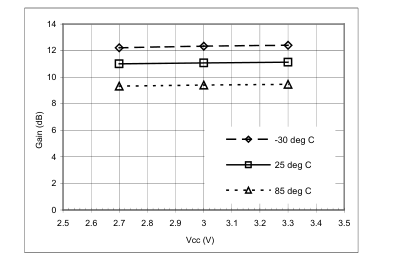
Figure 21. PCS Mixer Gain at 1960 MHz
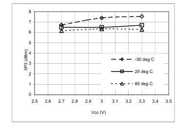
Figure 23. PCS Mixer IIP3 at 1960 MHz
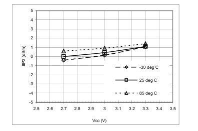
Figure 20. AMPS LNA IIP3 at 881 MHz
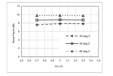
Figure 22. PCS Mixer Noise Figure at 1960 MHz
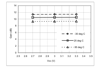
Figure 24. CELL CDMA Mixer Gain at 881 MHz
Page 16
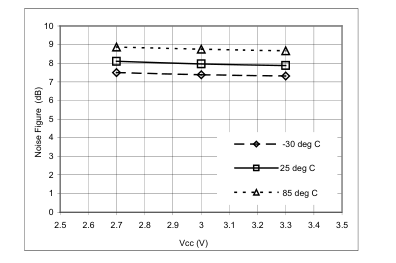
Figure 25. Cell CDMA Mixer Noise Figure at 881 MHz
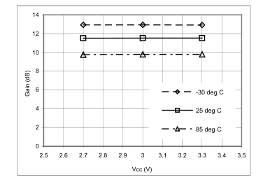
Figure 27. AMPS Mixer Gain at 881 MHz
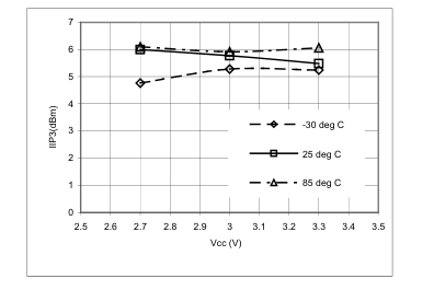
Figure 29. AMPS Mixer IIP3 at 881 MHz
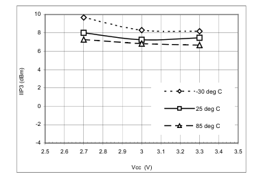
Figure 26. Cell CDMA Mixer IIP3 at 881 MHz
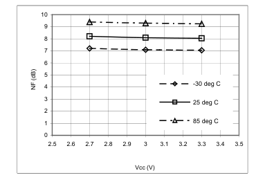
Figure 28. AMPS Mixer Noise Figure at 881 MHz
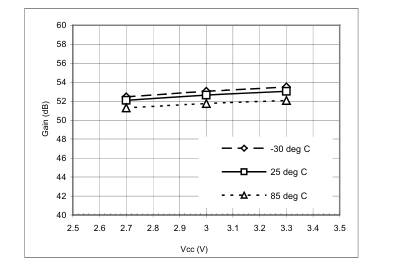
Figure 30. PCS VGA+IQ Gain (VCC = 2.5 V) at 210.38 MHz
Page 17
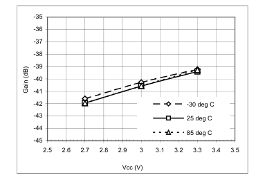
Figure 31. PCS VGA+IQ Gain (VCC = 0.5 V) at 210.38 MHz
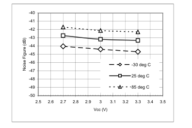
Figure 33. PCS VGA+I/Q IIP3 (VCC = 2.5 V) at 210.38 MHz
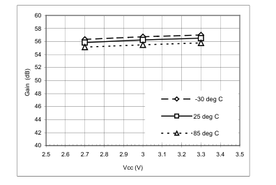
Figure 35. Cell CDMA VGA+IQ Gain (VCC = 2.5 V) at 85.38 MHz
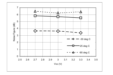
Figure 32. PCS VGA+I/Q Noise Figure (VCC = 2.5 V) at 210.38 MHz
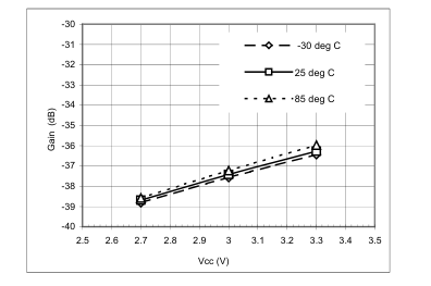
Figure 34. Cell CDMA VGA+IQ Gain (VCC = 0.5 V) at 85.38 MHz
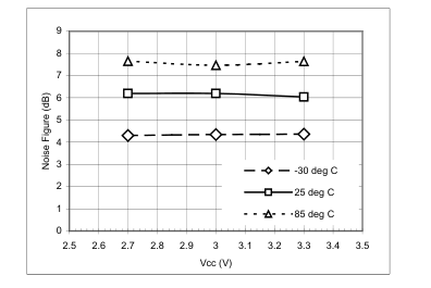
Figure 36. CDMA VGA+I/Q Noise Figure (VCC = 2.5 V) at 85.38 MHz
Page 18
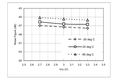
Figure 37. CDMA VGA+I/Q IIP3 (Vc = 2.5 V) at 85.38 MHz
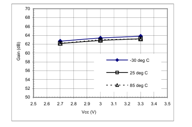
Figure 39. AMPS VGA+IQ Gain (Vc = 2.5 V) at 85.38 MHz
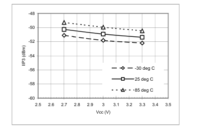
Figure 41. AMPS VGA+I/Q IIP3 (Vc = 2.5 V) at 85.38 MHz
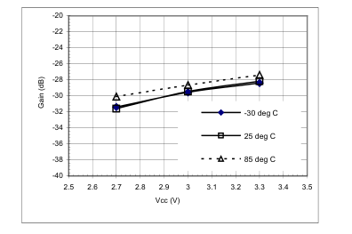
Figure 38. AMPS VGA+IQ Gain (Vc = 0.5 V) at 85.38 MHz
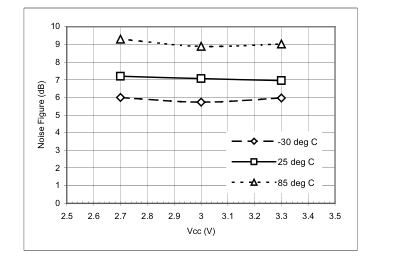
Figure 40. AMPS VGA+I/Q Noise Figure (Vc = 2.5 V) at 85.38 MHz
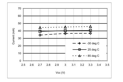
Figure 42. Supply Current in PCS Mode (LNA Bypassed)
Page 19
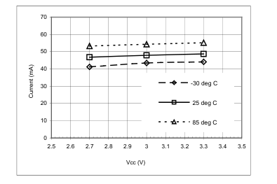
Figure 43. Supply Current in PCS Mode ( LNA ON)
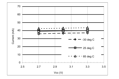
Figure 45. Supply Current in CELL CDMA Mode (LNA Bypassed)
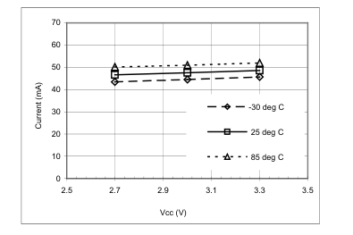
Figure 44. Supply Current in Cell CDMA Mode (LNA ON)
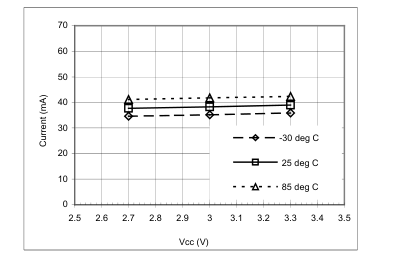
Figure 46. Supply Current in AMPS Mode
Page 20
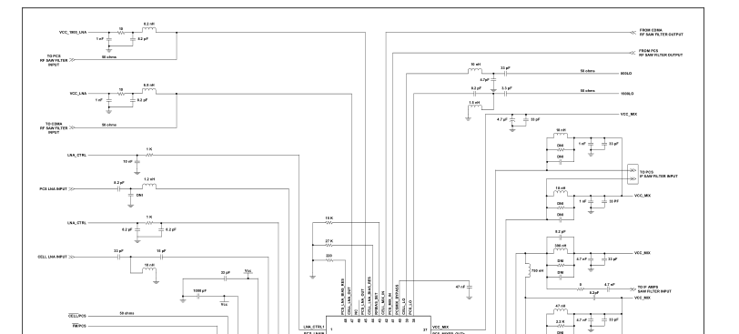
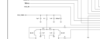
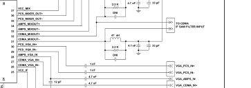
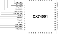
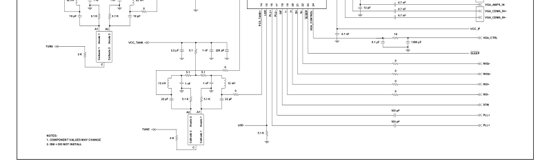
Figure 47. CX74001 Schematic Diagram
Page 21
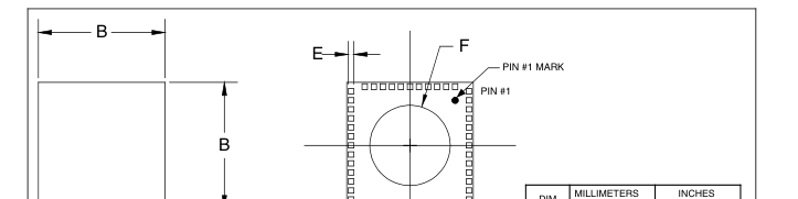
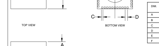
| DIM. | MILLIMETERS | INCHES | ||
| MIN. | MAX. | MIN. | MAX. | |
| A | 1.10 | 1.30 | 0.043 | 0.051 |
| B | 6.90 | 7.10 | 0.272 | 0.280 |
| C | 0.25 | 0.35 | 0.010 | 0.014 |
| D | 0.50 REF | 0.020 REF | ||
| E | 0.31 | 0.41 | 0.012 | 0.016 |
| F | R 2.225 REF | R 0.089 REF | ||
CNXT017
SIDE VIEW
Figure 48. Package Dimensions – 48-pin RFLGA Package
Page 22
Ordering Information
| Model Name | Manufacturing Part Number | Product Revision |
|---|---|---|
| Dual-band, tri-mode Rx ASIC | CX74001-12 |
© 2002, Skyworks Solutions, Inc. All Rights Reserved.
Information in this document is provided in connection with Skyworks Solutions, Inc. ("Skyworks") products. These materials are provided by Skyworks as a service to its customers and may be used for informational purposes only. Skyworks assumes no responsibility for errors or omissions in these materials. Skyworks may make changes to its products, specifications and product descriptions at any time, without notice. Skyworks makes no commitment to update the information and shall have no responsibility whatsoever for conflicts, incompatibilities, or other difficulties arising from future changes to its products and product descriptions.
No license, express or implied, by estoppel or otherwise, to any intellectual property rights is granted by this document. Except as may be provided in Skyworks’ Terms and Conditions of Sale for such products, Skyworks assumes no liability whatsoever.
THESE MATERIALS ARE PROVIDED "AS IS" WITHOUT WARRANTY OF ANY KIND, EITHER EXPRESS OR IMPLIED, RELATING TO SALE AND/OR USE OF SKYWORKS™ PRODUCTS INCLUDING WARRANTIES RELATING TO FITNESS FOR A PARTICULAR PURPOSE, MERCHANTABILITY, PERFORMANCE, QUALITY OR NON-INFRINGEMENT OF ANY PATENT, COPYRIGHT OR OTHER INTELLECTUAL PROPERTY RIGHT. SKYWORKS FURTHER DOES NOT WARRANT THE ACCURACY OR COMPLETENESS OF THE INFORMATION, TEXT, GRAPHICS OR OTHER ITEMS CONTAINED WITHIN THESE MATERIALS. SKYWORKS SHALL NOT BE LIABLE FOR ANY SPECIAL, INDIRECT, INCIDENTAL, OR CONSEQUENTIAL DAMAGES, INCLUDING WITHOUT LIMITATION, LOST REVENUES OR LOST PROFITS THAT MAY RESULT FROM THE USE OF THESE MATERIALS.
Skyworks™ products are not intended for use in medical, lifesaving or life-sustaining applications. Skyworks’ customers using or selling Skyworks™ products for use in such applications do so at their own risk and agree to fully indemnify Skyworks for any damages resulting from such improper use or sale.
RFLGA is a trademark of Conexant Systems, Inc.
The following are trademarks of Skyworks Solutions, Inc.: Skyworks™, the Skyworks symbol, and “Breakthrough Simplicity”™. Product names or services listed in this publication are for identification purposes only, and may be trademarks of third parties. Third-party brands and names are the property of their respective owners.
Additional information, posted at www.skyworksinc.com, is incorporated by reference.
Page 23

General Information: Skyworks Solutions, Inc. 4311 Jamboree Rd. Newport Beach, CA 92660-3007 www.skyworksinc.com