


 Download PDF
CX65100 SKYWORKS
Document overview
- PDF pages: 9
Technical content
Page 1

DATA SHEET
CX65100: 700 – 1000 MHz Linear Power Amplifier
Applications
- AMPS/CDMA/TDMA/GSM
- Repeaters
- WLL and ISM bands
- Mobile radio
- Paging
- Telematics
Features
- Typical POUT of 30 dBm
- High linearity
- Low power consumption
- Single +3.4 V supply
- LCC 8-pin, 8 x 8 mm package
VREF
Description
Skyworks CX65100 Power Amplifier (PA) is a fully matched, 8-pin Leadless Chip Carrier (LCC) surface mount module, developed for cellular, Wireless Local Loop (WLL), and Industrial, Scientific, Medical (ISM) applications. This small, power-efficient PA has a full 700 to 1000 MHz bandwidth coverage packed into a single compact package. All active circuitry in the module is contained in a single Gallium Arsenide (GaAs) Microwave Monolithic Integrated Circuit (MMIC). The CX65100 is manufactured with Skyworks Aluminum (Al) GaAs Heterojunction Bipolar Transistor (HBT) process, which allows for single supply operation while maintaining high efficiency and good linearity.
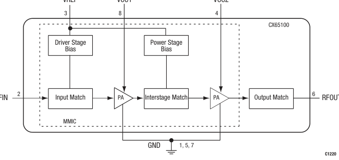
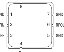
Figure 1 shows a functional block diagram for the CX65100. The device package and pinout for the 8-pin Leadless Chip Carrier (LCC) are shown in Figure 2. Signal pin assignments and functional pin descriptions are provided in Table 1.
VCC1
VCC2
RFIN
Figure 1. CX65100 Functional Block Diagram
Page 2
GND
RFIN
VREF
S384
Figure 2. CX65100 Pinout– 8-Pin LCC Package
(Top View)
Table 1. CX65100 Signal Descriptions
| Pin # | Name | Description | Pin # | Name | Description |
|---|---|---|---|---|---|
| 1 | GND | Ground | 5 | GND | Ground |
| 2 | RFIN | RF input | 6 | RFOUT | RF output |
| 3 | VREF | Reference voltage | 7 | GND | Ground |
| 4 | VCC2 | Supply voltage | 8 | VCC1 | Supply voltage |
Technical Description
The CX65100 is comprised of two amplifier stages. The matching circuits for the input stage, inter-stage, and output stage are contained within the device. The bias circuits for both input and output stages are included within the device for optimum temperature tracking performance. The CX65100 is internally matched for optimum linearity and efficiency. The input and output stages are independently supplied using the VCC1 and VCC2 supply lines, pins 8 and 4 respectively. The bias reference voltage is supplied using a common VREF (pin 3) line.
Package and Handling Information
Since the device package is sensitive to moisture absorption, it is baked and vacuum packed before shipping. Instructions on the shipping container label regarding exposure to moisture after the container seal is broken must be followed. Otherwise, problems related to moisture absorption may occur when the part is subjected to high temperature during solder assembly. If the part is attached in a reflow oven, the temperature ramp rate should not exceed 5 °C per second. Maximum temperature should not exceed 225 °C and the time spent at a temperature that exceeds 210 °C should be limited to less than 10 seconds. If the part is manually attached, precaution should be taken to
ensure that the part is not subjected to a temperature that exceeds 300 °C for more than 10 seconds. Care must be taken when attaching this product, whether it is done manually or in a production solder reflow environment. Production quantities of this product are shipped in a standard tape and reel format. For packaging details, refer to the Skyworks Application Note, Tape and Reel, document number 101568.
Electrical and Mechanical Specifications
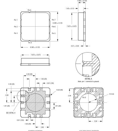
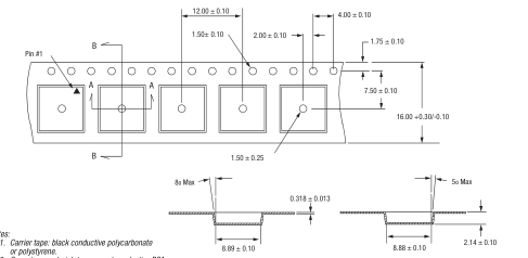
The absolute maximum ratings of the CX65100 are provided in Table 2. The recommended operating conditions are specified in Table 3 and electrical specifications are provided in Table 4. Typical performance characteristics over temperature of the CX65100 are illustrated in Figures 3 through 8. Figure 9 shows the package dimensions for the 8-pin CX65100 LCC and Figure 10 provides the tape and reel dimensions.
Electrostatic Discharge (ESD) Sensitivity
The CX65100 is a static-sensitive electronic device. Do not operate or store near strong electrostatic fields. Take proper ESD precautions.
August 13, 2004 • Skyworks Proprietary and Confidential information • Products and product information are subject to change without notice • 101471F
Page 3
Table 2. CX65100 Absolute Maximum Ratings
| Parameter | Symbol | Min | Typical | Max | Units |
|---|---|---|---|---|---|
| RF input power | PIN | 2 | dBm | ||
| Supply voltage | VCC | 4.5 | V | ||
| Reference voltage | VREF | 3.3 | V | ||
| Case operating temperature | TC | –40 | +85 | °C | |
| Storage temperature | TST | –55 | +125 | °C |
Note: Exposure to maximum rating conditions for extended periods may reduce device reliability. There is no damage to device with only one parameter set at the limit and all other parameters set at or below their nominal values.
Table 3. CX65100 Recommended Operating Conditions
| Parameter | Symbol | Min | Typical | Max | Units |
|---|---|---|---|---|---|
| Supply voltage | VCC | 3.4 | V | ||
| Reference voltage | VREF | 3.2 | V | ||
| Operating frequency | FO | 700 | 900 | 1000 | MHz |
Table 4. CX65100 Electrical Characteristics (VCC = 3.4 V, VREF = 3.2 V, Frequency = 900 MHz, TC = 25 °C, unless otherwise noted)
| Parameter | Symbol | Test Conditions | Min | Typical | Max | Units |
|---|---|---|---|---|---|---|
| Analog Inputs | ||||||
| Frequency range | 700 | 900 | 1000 | MHz | ||
| Quiescent current | IQ | 110 | 140 | mA | ||
| Small signal gain | G | PIN = –15 dBm | 28 | 30 | dB | |
| Output power | POUT | PIN = 1 dBm | 28 | 30 | dBm | |
| Efficiency | PAE | PIN = 1 dBm | 40 | 45 | % | |
| Noise Figure (NF) | NF | 4 | 6 | dB | ||
| Output IP3 | OIP3 | Two tones with 100 kHz spacing, PIN = –10 dBm per tone | 32.5 | 39.0 | dBm | |
Note: The above specifications apply only to the 900 MHz operating frequency.
Page 4
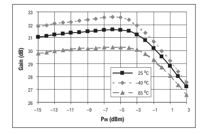
Figure 3. Typical Gain vs PIN Over Temperature (Frequency = 900 MHz)
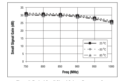
Figure 5. Typical Small Signal Gain vs Frequency Over
Temperature
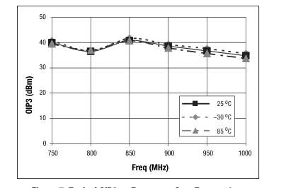
Figure 7. Typical OIP3 vs Frequency Over Temperature
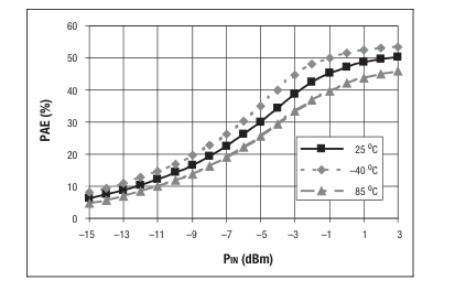
Figure 4. Typical PAE vs PIN Over Temperature (Frequency = 900 MHz)
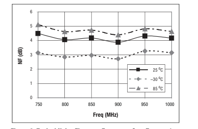
Figure 6. Typical Noise Figure vs Frequency Over Temperature
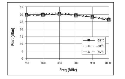
Figure 8. Typical POUT vs Frequency Over Temperature
August 13, 2004 • Skyworks Proprietary and Confidential information • Products and product information are subject to change without notice • 101471F
Page 5
COPPER BOTTOM
SOLDER MASK BOTTOM
The bottom solder mask thickness = 0.063 maximum
C1201
All measurements are in millimeters
Figure 9. CX65100 8-Pin LCC Package Dimensions
Notes:
- Cover tape material: transparent conductive PSA.
A
B
- All measurements are in millimeters.
C1221
Figure 10. CX65100 8-Pin LCC Tape and Reel Dimensions
Page 6
Evaluation Board Description
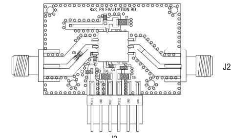
Skyworks CX65100 Evaluation Board is used to test the performance of the CX65100 PA. The Evaluation Board schematic diagram is shown in Figure 11. The schematic shows the basic design of the board for the 700 to 1000 MHz range. Figure 12 provides the Evaluation Board assembly diagram. Figure 13 provides the Evaluation Board layer detail.
Circuit Design Considerations The following design considerations are general in nature and must be followed regardless of final use or configuration 1. Paths to ground should be made as short as possible. 2. The ground pad of the CX65100 PA has special electrical and thermal grounding requirements. This pad is the main thermal conduit for heat dissipation. Since the circuit board acts as the heat sink, it must shunt as much heat as possible from the amplifier. As such, design the connection to the ground pad to dissipate the maximum wattage produced to the circuit board. Multiple vias to the grounding layer are required. 3. Three external output bypass capacitors (150 pF, 0.01 µF, and
4.7 µF) are required on the VCC1 (pin 8) supply input. The same three capacitors are also required on the VCC2 (pin 4) supply input. All three capacitors should be placed in parallel between the supply line and ground. Also, 0.01 µF and 4.7 µF bypass capacitors are required on the VREF input (pin 3). See Figure 11 for a detailed diagram. 4. VCC1 (pin 8) and VCC2 (pin 4) may be connected together at the supply.
- At the RF input (pin 2), a DC blocking capacitor is required. 6. The RF output includes an onboard internal DC blocking capacitor. All impedance matching is provided internally. Therefore, the application only needs to provide a good 50 Ω load.
Testing Procedure Use the following procedure to set up the CX65100 Evaluation Board for testing. Refer to Figure 14 for guidance: 1. Connect a +3.4 V supply voltage to VCC1 and VCC2, and +3.2 V supply voltage to VREF. If available, enable the current limiting function of the power supplies to 1.0 A for the +3.4 V supply current and 30 mA for the +3.2 V supply current. 2. Connect a signal generator to the RF signal input port. Set it to the desired RF frequency at a power level of 2 dBm or less to the Evaluation Board but do NOT enable the RF signal. 3. Connect a spectrum analyzer to the RF signal output port. 4. Enable the power supply. 5. Enable the RF signal.
- Take measurements.
Caution: If the input signal exceeds the rated power, the CX65100 Evaluation Board can be permanently damaged.
August 13, 2004 • Skyworks Proprietary and Confidential information • Products and product information are subject to change without notice • 101471F
Page 7
+3.4 V
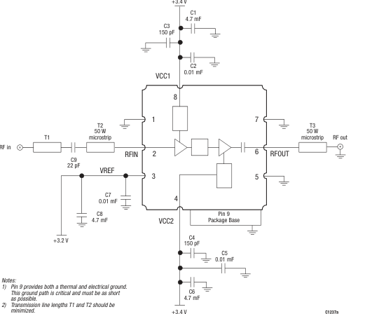
Figure 11. Evaluation Board Schematic, 700 MHz to 1000 MHz
J1 (RF In)
J2 (RF Out)
J3
C1257
Figure 12. Evaluation Board Assembly Diagram
Page 8
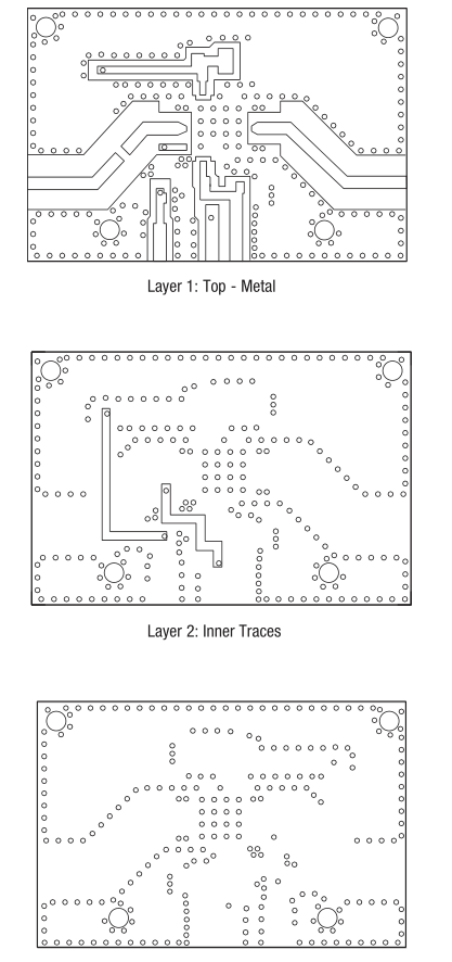
Layer 3: Solid Ground Plane
C1253a
Figure 13. Evaluation Board Layer Detail
August 13, 2004 • Skyworks Proprietary and Confidential information • Products and product information are subject to change without notice • 101471F
Page 9
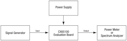
C1240a
Figure 14. CX65100 Evaluation Board Testing Configuration
Ordering Information
| Model Name | Manufacturing Part Number | Evaluation Kit Part Number |
|---|---|---|
| CX65100 700-1000 MHz Linear Power Amplifier | CX65100-11 | TW10-D802 |
Copyright © 2001, 2002, 2004, Skyworks Solutions, Inc. All Rights Reserved.
Information in this document is provided in connection with Skyworks Solutions, Inc. (“Skyworks”) products. These materials are provided by Skyworks as a service to its customers and may be used for informational purposes only by the customer. Skyworks assumes no responsibility for errors or omissions in these materials. Skyworks may make changes to its documentation, products, specifications and product descriptions at any time, without notice. Skyworks makes no commitment to update the information and shall have no responsibility whatsoever for conflicts, incompatibilities, or other difficulties arising from future changes to its documentation, products, specifications and product descriptions.
No license, express or implied, by estoppel or otherwise, to any intellectual property rights is granted by or under this document. Except as may be provided in Skyworks Terms and Conditions of Sale for such products, Skyworks assumes no liability whatsoever in association with its documentation, products, specifications and product descriptions.
THESE MATERIALS ARE PROVIDED “AS IS” WITHOUT WARRANTY OF ANY KIND, EITHER EXPRESS OR IMPLIED OR OTHERWISE, RELATING TO SALE AND/OR USE OF SKYWORKS PRODUCTS INCLUDING WARRANTIES RELATING TO FITNESS FOR A PARTICULAR PURPOSE, MERCHANTABILITY, PERFORMANCE, QUALITY OR NON-INFRINGEMENT OF ANY PATENT, COPYRIGHT OR OTHER INTELLECTUAL PROPERTY RIGHT. SKYWORKS FURTHER DOES NOT WARRANT THE ACCURACY OR COMPLETENESS OF THE INFORMATION, TEXT, GRAPHICS OR OTHER ITEMS CONTAINED WITHIN THESE MATERIALS. SKYWORKS SHALL NOT BE LIABLE FOR ANY DAMAGES, INCLUDING SPECIAL, INDIRECT, INCIDENTAL, OR CONSEQUENTIAL DAMAGES, INCLUDING WITHOUT LIMITATION, LOST REVENUES OR LOST PROFITS THAT MAY RESULT FROM THE USE OF THESE MATERIALS WHETHER OR NOT THE RECIPIENT OF MATERIALS HAS BEEN ADVISED OF THE POSSIBILITY OF SUCH
DAMAGE.
Skyworks products are not intended for use in medical, lifesaving or life-sustaining applications. Skyworks customers using or selling Skyworks products for use in such applications do so at their own risk and agree to fully indemnify Skyworks for any damages resulting from such improper use or sale.
The following are trademarks of Skyworks Solutions, Inc.: Skyworks™, the Skyworks logo, and Breakthrough Simplicity™. Product names or services listed in this publication are for identification purposes only, and may be trademarks of Skyworks or other third parties. Third-party brands and names are the property of their respective owners. Additional information, posted at www.skyworksinc.com, is incorporated by reference.