
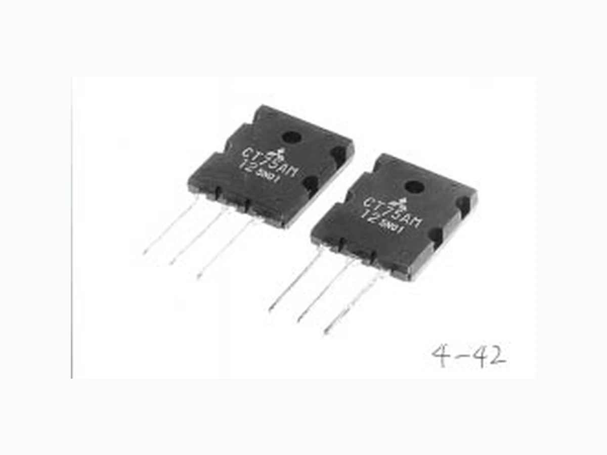
CT75AM-12 RENESAS
Document overview
- Manufacturer or author: Provided By www.digicamel.com(FREE DATASHEET DOWNLOAD SITE)
- PDF pages: 4
Technical content
Regarding the change of names mentioned in the document, such as Mitsubishi Electric and Mitsubishi XX, to Renesas Technology Corp. The semiconductor operations of Hitachi and Mitsubishi Electric were transferred to Renesas Technology Corporation on April 1st 2003. These operations include microcomputer, logic, analog and discrete devices, and memory chips other than DRAMs (flash memory, SRAMs etc.) Accordingly, although Mitsubishi Electric, Mitsubishi Electric Corporation, Mitsubishi Semiconductors, and other Mitsubishi brand names are mentioned in the document, these names have in fact all been changed to Renesas Technology Corp. Thank you for your understanding. Except for our corporate trademark, logo and corporate statement, no changes whatsoever have been made to the contents of the document, and these changes do not constitute any alteration to the contents of the document itself. Note : Mitsubishi Electric will continue the business operations of high frequency & optical devices and power devices. Renesas Technology Corp. Customer Support Dept. April 1, 2003 To all our customers
Feb.1999 CT75AM-12 600 ±20 ±30 150 300 –40 ~ +150 –40 ~ +150 9.8 V V V A A W g \ High Speed Switching \ Low VCE Saturation Voltage VCES VGES VGEM IC ICM PC Tj Tstg OUTLINE DRAWING Dimensions in mm MITSUBISHI INSULATED GATE BIPOLAR TRANSISTOR CT75AM-12 GENERAL INVERTER • UPS USE APPLICATION AC & DC motor controls, General purpose invert- ers, UPS, Power supply switching, Servo controls, etc. TO-3PL ConditionsSymbol Collector-emitter voltage Gate-emitter voltage Peak gate-emitter voltage Collector current Collector current (Pulsed) Maximum power dissipation Junction temperature Storage temperature Weight MAXIMUM RATINGS (Tc = 25°C) Parameter Ratings Unit VGE = 0V VCE = 0V VCE = 0V Typical value 20MAX. 5 2620.6MIN. 0.5 2.5 4.0 φ 3.2 5.45 5.45 1 2 3 q GATE w COLLECTOR e EMITTER r COLLECTOR wr q e
Feb.1999 V (BR) CES IGES ICES VGE(th) VCE(sat) C ies C oes C res td (on) tr td (off) tf R th (j-c) MITSUBISHI INSULATED GATE BIPOLAR TRANSISTOR CT75AM-12 GENERAL INVERTER • UPS USE 600 4.5 V µA mA V V pF pF pF ns ns ns ns °C/W 6.0 2.5 3100 400 130 265 175 245 ±0.5 7.5 3.0 0.42 I C = 1mA, VGE = 0V VGE = ±30V, VCE = 0V VCE = 600V, VGE = 0V IC = 7.5mA, VCE = 10V IC = 75A, VGE = 15V VCE = 25V, VGE = 0V, f = 1MHz VCC = 300V, Resistance load, IC = 75A, VGE = 15V, RGE = 10Ω Junction to case 0 4 8 12 16 20 150A 30A 75A Tj = 25°C 100 02468 1 0 Tj = 25°C VGE = 20V PC = 300W 15V 12V 10V 11V OUTPUT CHARACTERISTICS (TYPICAL) COLLECTOR-EMITTER VOLTAGE V CE (V) COLLECTOR CURRENT I C (A) COLLECTOR-EMITTER SATURATION VOLTAGE CHARACTERISTICS (TYPICAL) GATE-EMITTER VOLTAGE V GE (V) COLLECTOR-EMITTER SATURATION VOLTAGE V CE(sat) (V) ELECTRICAL CHARACTERISTICS (Tj = 25°C) Symbol UnitParameter Test conditions Limits Min. Typ. Max. Collector-emitter breakdown voltage Collector-emitter leakage current Gate-emitter leakage current Gate-emitter threshold voltage Collector-emitter saturation voltage Input capacitance Output capacitance Reverse transfer capacitance Turn-on delay time Rise time Turn-off delay time Fall time Thermal resistance PERFORMANCE CURVES
Feb.1999 MITSUBISHI INSULATED GATE BIPOLAR TRANSISTOR CT75AM-12 GENERAL INVERTER • UPS USE 0 40 80 120 160 200 VCE = 200V 300V 0 2 04 06 08 0 1 0 0 VGE = 15V Tj = 25°C 100 0 4 8 12 16 20 VCE = 10V Tj = 25°C 101 102 103 104 10035 7 2 1 0 135 7 2 1 0 235 7 3 2 Tj = 25°C VGE = 0V f = 1MHZ Cies Coes Cres 10–5 10–3 10–2 10–1 100 23 57 23 5710–123 57 10–210–3 100 23 57 101 10–3 10–2 23 57 10–323 57 10–4 100 10123 5 7 1 0 223 5 7101 102 103 td(off) td(on) tf tr Tj = 25°C VCC = 300V VGE = 15V R G = 10Ω COLLECTOR-EMITTER SATURATION VOLTAGE CHARACTERISTICS (TYPICAL) COLLECTOR CURRENT I C (A) COLLECTOR-EMITTER SATURATION VOLTAGE VCE (V) SWITCHING TIME-COLLECTOR CURRENT CHARACTERISTIC (TYPICAL) COLLECTOR CURRENT I C (A) SWITCHING TIME (ns) GATE CHARGE Q g (nc) GATE-EMITTER VOLTAGE VS. GATE CHARGE CHARACTERISTIC (TYPICAL) GATE-EMITTER VOLTAGE V GE (V) COLLECTOR CURRENT VS. GATE EMITTER VOLTAGE CHARACTERISTIC (TYPICAL) GATE-EMITTER VOLTAGE V GE (V) COLLECTOR CURRENT I C (A) CAPACITANCE VS. COLLECTOR-EMITTER VOLTAGE CHARACTERISTIC (TYPICAL) COLLECTOR-EMITTER VOLTAGE V CE (V) CAPACITANCE Cies, Coes, Cres (pF) PULSE WIDTH tw (s) TRANSIENT THERMAL IMPEDANCE CHARACTERISTICS (TYPICAL) TRANSIENT THERMAL IMPEDANCE Z th (j–c)