
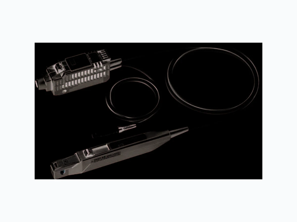
CURRENT PROBE CT6700/CT6701
Document overview
- Manufacturer or author: HIOKI
- PDF pages: 4
Technical content
CURRENT PROBE CT6700/CT6701 Current probes are key to the successful design of electrical devices, medical instruments, and electronic parts. In combination with an oscilloscope or HIOKI MEMORY HiCORDER, probes are ideal for measuring currents with high accuracy and wide bandwidths, making them indispensable tools for evaluating current consumption and control current. In recent years, customers are seeking current probes with high sensitivity to increase the accuracy of design and verification. To further enhance our rich lineup of current probes, HIOKI now delivers two new, highly-sensitive current probes that can measure low level currents from 1 mA. CT6701 DC to 120MHz, 5A MAX CT6700 DC to 50MHz, 5A MAX 10× the sensitivity of conventional probes A separate power supply is required when using the CT6700/CT6701. Connection image Observe low current waveforms of 1 mA
Input: 1 mAp-p, 1 kHz, sine wave Oscilloscope: Bandwidth 2 GHz (Bandwidth limit 20 MHz), 1 mV/div The output rate for the CT6700/ CT6701 is 1 V/A. When 1 mA is measured, it can output 1 mV. This is ten times the sensitivity of our legacy* 1 models. Now, even 1 mA waveforms can be clearly captured.*2 Low level currents can only be clearly captured by instruments that deliver a good S/N ratio. Because the output rate is now 1 V/A (10x than that of legacy models), you can observe waveforms even if the oscilloscope's range is 1/10 than that of legacy products. By allowing for range selection with leeway for the S/N ratio, you can clearly observe signals that previously were buried in noise. *1: CURRENT PROBE 3273-50/3276 Output rate 0.1 V/A, 30 A MAX *2: When measuring low level currents, in addition to noise from the current probe itself, there is also influence from external noise or noise from the connected meter. 10x Sensitivity Clearly observe even 1 mA waveforms Improved S/N Ratio: Measure even the extremely low current signals buried in noise Analyze currents in finer detail Legacy models CT6701 Input: 20 mAp-p, 1 kHz, sine wave Oscilloscope: Bandwidth 2 GHz (No bandwidth limitation), 10 mV/div Input: 20 mAp-p, 1 kHz, square wave Oscilloscope: Bandwidth 2 GHz ( No bandwidth limitation ), 10 mV/div Legacy models Legacy models CT6700 CT6700 Oscilloscope usage range: 1 mV/div Oscilloscope usage range: 1 mV/div Oscilloscope usage range: 10 mV/div Oscilloscope usage range: 10 mV/div
Built for Demanding Applications The sensor has been redesigned, making it more compact and easier to handle, in a form that fits perfectly in your hand. The ergonomic structure is ideal for situations with complex electrical circuit design and wiring. Slim Sensor With the CT6700/CT6701, you can automatically perform the zero-adjustment, which must be done before use, by pressing a single button. By pressing and holding the button for demagnetization, you can cancel an offset margin of error after measuring a large current. Automatic Zero-Adjustment and Demagnetization in One Button Solenoid valves Relay control current Condenser current Waveform of an inverter when switched ON Evaluation of LED light driving circuits Compact motors The warning lamp will flash if a current exceeding the rating is input. "JAW UNLOCKED" will display and the warning lamp will light up if the sensor is unlocked when clamped. OVERLOAD Warning Sensor (Actual size) JAW UNLOCKED Warning Warning Features The BNC connector does not need to be rotated when connecting to an oscilloscope or recorder. Insert the connector until it automatically locks into place. To disconnect it, just pull the unlock lever toward you. One-touch Disconnection from the BNC Terminal Measure the current of automobile electronic parts Evaluate the current characteristics of circuit components Evaluate high-speed switching elements Streamlining Measurement Measure switching elements that drive devices such as LEDs and motors, including the ON/OFF response of semiconductors that operate at high speeds, ripple waveforms, and switching loss. Observe control currents, which flow through automobile electronic parts such as compact motors, on the mA order. When testing for the correct functioning of built-in circuits, you can reliably catch noise waveforms with a wide frequency bandwidth. Analyze currents in finer detail Current Threshold
81 Koizumi, Ueda, Nagano, 386-1192, Japan
TEL +81-268-28-0562 FAX +81-268-28-0568 http://www.hioki.com / E-mail: os-com@hioki.co.jp HIOKI USA CORPORATION TEL +1-609-409-9109 FAX +1-609-409-9108 http://www.hiokiusa.com / E-mail: hioki@hiokiusa.com All information correct as of Dec. 11, 2014. All specifications are subject to change without notice. CT6700E2-4ZM Printed in Japan DISTRIBUTED BYHIOKI (Shanghai) SALES & TRADING CO., LTD. TEL +86-21-63910090 FAX +86-21-63910360 http://www.hioki.cn / E-mail: info@hioki.com.cn HIOKI INDIA PRIVATE LIMITED TEL +91-124-6590210 FAX +91-124-6460113 E-mail: hioki@hioki.in HIOKI SINGAPORE PTE. LTD. TEL +65-6634-7677 FAX +65-6634-7477 E-mail: info-sg@hioki.com.sg HIOKI KOREA CO., LTD. TEL +82-42-936-1281 FAX +82-42-936-1284 E-mail: info-kr@hioki.co.jp Note: Company names and Product names appearing in this catalog are trademarks or registered trademarks of various companies. A separate power supply is required when using the CT6700/CT6701. Specifications (Product warranty period : 1 Year) CT6700 CT6701 Frequency range DC to 50 MHz (-3dB) (Refer to the frequency characteristics graph below.) DC to 120 MHz (-3dB) (Refer to the frequency characteristics graph below.) Rise time (10% to 90%) 7.0 ns or less 2.9 ns or less Maximum rated current 5 A rms (DC, and sine wave) (Refer to the frequency derating properties graph below.) Maximum peak current ±7.5 A peak (non-continuous) Diameter of measurable conductors 5 mm dia. or less Measurable conductors Insulated conductors Output voltage rate 1 V/A Amplitude accuracy ±1%rdg. typical ±1 mV, ±3.0%rdg. ±1 mV (DC, 45 to 66 Hz sine wave, 0 to 5 A rms) Output resistance 50 Ω ±10% (DC) Noise 60 μA rms typical, 75 μA rms max (for 30 MHz band measuring instrument) Temperature coefficient for sensitivity ±2%rdg. or less (After automatic zero-adjustment with 50 Hz 5 A rms input, except at 23±5°C) Maximum rated power 3.2 VA (with continuous maximum input) Supply voltage ±12 V Operating temperature and humidity range 0 to +40°C, 80% RH or less (no condensation) Storage temperature and humidity range -10 to +50°C, 80% RH or less (no condensation) Location for use Indoor, pollution degree 2, altitude up to 2000 m Effect of external magnetic fields 20 mA max - DC and 60 Hz, magnetic field of 400 A/m 5 mA max - DC and 60 Hz, magnetic field of 400 A/m Effect of radiated radio-frequency electromagnetic field ±10 mA max (at 3 V/m) Effect of conducted radio-frequency electromagnetic field ±10 mA max (at 3 V) DEMAG/AUTO ZERO function Demagnetization, automatic zero-adjustment JAW UNLOCKED detection LED lights up when the opening mechanism of the sensor head is unlocked. OVERLOAD detection LED flashes to warn that the input is in excess of ratings Accuracy warranty period 1 year (Opening/closing up to 10,000 times) Cord lengths Sensor cord: 1.5 m (4.92 ft), Power cord: 1.0 m (3.28 ft) Accessories Instruction manual, Carrying case Lineup and options CURRENT PROBE CT6700 DC to 50MHz, 5A MAX POWER SUPPLY 3269 Supports up to 4 current probes POWER SUPPLY 3272 Supports 2 current probes CURRENT PROBE CT6701 DC to 120MHz, 5A MAX Frequency characteristics: CT6700 (typ.) Gain [dB] Frequency[Hz] -40 -30 -20 -10 100M 1G1M10k1001 Frequency characteristics: CT6701 (typ.) Gain [dB] Frequency[Hz] -40 -30 -20 -10 100M 1G1M10k1001 Frequency derating: CT6700 (typ.) Maximum input current [A] Frequency[Hz] 100M 1G10M1M100k10k1k100 Frequency[Hz] Input impedance: CT6700 (typ.) Input impedance [Ω] 0.001 0.01 0.1 100M 1G10M1M100k10k1k100 Input impedance: CT6701 (typ.) Input impedance [Ω] Frequency[Hz] 0.001 0.01 0.1 100M 1G10M1M100k10k1k100 Maximum input current [A] Frequency[Hz] 100M 1G10M1M100k10k1k100 Frequency derating: CT6701 (typ.) *About the 3272 Power Supply When using CT6700/CT6701 and a different sensor simultaneously, please note that you may not be able to use two sensors at once depending on the current consumption. Please check the specifications of the corresponding sensor. Side Unit: mm 26 40 Diameter of measurable conductors: φ5 Top 2918 8317 155