
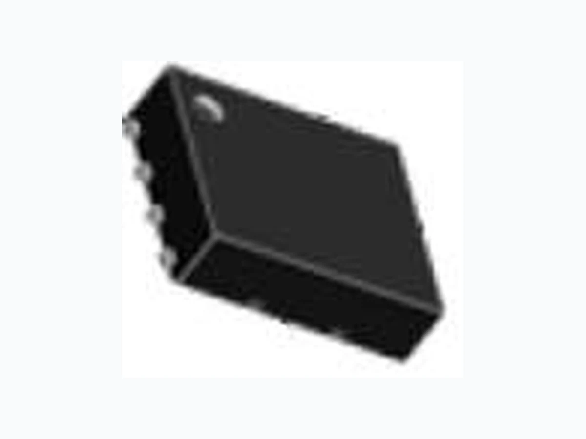
CSD95375Q4M Synchronous Buck NexFET Power Stage datasheet (Rev. A)
Document overview
- Manufacturer or author: Texas Instruments, Incorporated [SLPS430,A]
- PDF pages: 22
Technical content
+Is1 -Is2 +NTC -NTC +Is2 -Is2 PWM2 VOUT SS RT VCC VOUT VOUT VIN Multi-Phase Controller CSD95375 CSD95375 PGND 0 5 10 15 20 25 100 Output Current (A) Efficiency (%) Power Loss (W) VDD = 5V VIN = 12V VOUT = 1.8V LOUT = .29µH fSW = 500kHz TA = 25ºC G001 Product Folder Sample & Buy T echnical Documents Tools & Software Support & Community CSD95375Q4M SLPS430A –AUGUST 2013–REVISED AUGUST 2014 CSD95375Q4MSynchronousBuckNexFET™ PowerStage
1 Features 2 Applications
1• 93% System Efficiency at 15 A • Ultrabook/Notebook DC/DC Converters
- Max Rated Continuous Current 25 A, Peak 60 A • Multiphase Vcore and DDR Solutions
- High Frequency Operation (up to 2 MHz) • Point of Load Synchronous Buck in Networking, Telecom, and Computing Systems• High Density - SON 3.5 × 4.5-mm Footprint
- Ultra-Low Inductance Package 3 Description• System Optimized PCB Footprint The CSD95375Q4M NexFET™ Power Stage is a• Ultra-Low Quiescent (ULQ) Current Mode highly optimized design for use in a high power, high
- 3.3 V and 5 V PWM Signal Compatible density Synchronous Buck converter. This product integrates the driver IC and NexFET technology to• Diode Emulation Mode with FCCM complete the power stage switching function. The• Tri-State PWM Input driver IC has a built-in selectable diode emulation
- Integrated Bootstrap Diode function that enables DCM operation to improve light load efficiency. In addition, the driver IC supports• Shoot Through Protection ULQ mode that enables Connected Standby for• RoHS Compliant – Lead-Free Terminal Plating Windows™ 8. With the PWM input in tri-state,
- Halogen Free quiescent current is reduced to 130 µA, with immediate response. When SKIP# is held at tri-state, the current is reduced to 8 µA (typically 20 µs is required to resume switching). This combination produces a high current, high efficiency, and high speed switching device in a small 3.5 × 4.5-mm outline package. In addition, the PCB footprint has been optimized to help reduce design time and simplify the completion of the overall system design. Device Information(1) Device Media Qty Package Ship CSD95375Q4M 13-Inch Reel 2500 SON 3.5 × 4.5 mm Tape and Plastic Package ReelCSD95375Q4MT 7-Inch Reel 250 (1) For all available packages, see the orderable addendum at the end of the data sheet. SPACER Application Diagram Typical Power Stage Efficiency and Power Loss An IMPORTANT NOTICE at the end of this data sheet addresses availability, warranty, changes, use in safety-critical applications, intellectual property matters and other important disclaimers. PRODUCTION DATA.
SLPS430A –AUGUST 2013–REVISED AUGUST 2014 www.ti.com Table of Contents
4 Revision History
Changes from Original (August 2013) to Revision A Page
2 Submit Documentation Feedback Copyright © 2013–2014, Texas Instruments Incorporated
SKIP# VSW VDD PGND BOOT BOOT_R CSD95375Q4M www.ti.com SLPS430A –AUGUST 2013–REVISED AUGUST 2014
5 Pin Configuration
DESCRIPTION
NO. NAME 1 SKIP# This pin enables the Diode Emulation function. When this pin is held Low, Diode Emulation Mode is enabled for the Sync FET. When SKIP# is High, the CSD95375Q4M operates in Forced Continuous Conduction Mode. A tri-state voltage on SKIP# puts the driver into a very low power state. 2 VDD Supply Voltage to Gate Drivers and internal circuitry.
3 PGND Power Ground, Needs to be connected to Pin 9 and PCB
4 VSW Voltage Switching Node – pin connection to the output inductor. 5 VIN Input Voltage Pin. Connect input capacitors close to this pin. 6 BOOT_R Bootstrap capacitor connection. Connect a minimum 0.1 µF 16 V X5R, ceramic cap from BOOT to BOOT_R pins. The bootstrap capacitor provides the charge to turn on the Control FET. The bootstrap diode is integrated. Boot_R is7 BOOT internally connected to VSW. 8 PWM Pulse Width modulated tri-state input from external controller. Logic Low sets Control FET gate low and Sync FET gate high. Logic High sets Control FET gate high and Sync FET gate Low. Open or High Z sets both MOSFET gates low if greater than the Tri-State Shutdown Hold-off Time (t3HT)
9 PGND Power Ground
Copyright © 2013–2014, Texas Instruments Incorporated Submit Documentation Feedback 3
SLPS430A –AUGUST 2013–REVISED AUGUST 2014 www.ti.com
6 Specifications
6.1 Absolute Maximum Ratings (1)
TA = 25°C (unless otherwise noted) VALUE UNIT MIN MAX VIN to PGND –0.3 20 V VSW to PGND , VIN to VSW –0.3 20 V VSW to PGND, VIN to VSW (<10 ns) –7 23 V VDD to PGND –0.3 6 V PWM, SKIP# to PGND –0.3 6 V BOOT to PGND –0.3 25 V BOOT to PGND (<10 ns) –2 28 V BOOT to BOOT_R –0.3 6 V BOOT to BOOT_R (duty cycle <0.2%) Human Body Model (HBM) 2000 V ESD Rating Charged Device Model (CDM) 500 V Power Dissipation, PD 8 W Operating Temperature Range, TJ –40 150 °C Storage Temperature Range, Tstg –55 150 °C (1) Stresses above those listed in "Absolute Maximum Ratings" may cause permanent damage to the device. These are stress ratings only and functional operation of the device at these or any other conditions beyond those indicated under "Recommended Operating Conditions" is not implied. Exposure to Absolute Maximum rated conditions for extended periods may affect device reliability.
6.2 Recommended Operating Conditions
TA = 25° (unless otherwise noted) MIN MAX UNIT Gate Drive Voltage, VDD 4.5 5.5 V Input Supply Voltage, VIN 16 V Continuous Output Current, IOUT VIN = 12 V, VDD = 5 V, VOUT = 1.8 V, 25 A ƒSW = 500 kHz, LOUT = 0.29 µH(1) Peak Output Current, IOUT-PK (2) 60 A Switching Frequency, ƒSW CBST = 0.1 µF (min) 2000 kHz On Time Duty Cycle 85% Minimum PWM On Time 40 ns Operating Temperature –40 125 °C (1) Measurement made with six 10-µF (TDK C3216X5R1C106KT or equivalent) ceramic capacitors placed across VIN to PGND pins. (2) System conditions as defined in Note 1. Peak Output Current is applied for tp = 10 ms, duty cycle ≤1%
6.3 Thermal Information
TA = 25°C (unless otherwise noted) THERMAL METRIC MIN TYP MAX UNIT RθJC Junction-to-Case Thermal Resistance (Top of package)(1) 22.8 °C/W RθJB Junction-to-Board Thermal Resistance(2) 2.5 (1) RθJC is determined with the device mounted on a 1-inch² (6.45 -cm²), 2-oz (.071-mm thick) Cu pad on a 1.5-inches × 1.5-inches, 0.06-inch (1.52-mm) thick FR4 board. (2) RθJB value based on hottest board temperature within 1-mm of the package.
4 Submit Documentation Feedback Copyright © 2013–2014, Texas Instruments Incorporated
www.ti.com SLPS430A –AUGUST 2013–REVISED AUGUST 2014
6.4 Electrical Characteristics
TA = 25°C, VDD = POR to 5.5 V (unless otherwise noted) PARAMETER TEST CONDITIONS MIN TYP MAX UNIT PLOSS VIN = 12 V, VDD = 5 V, VOUT = 1.8 V, IOUT = 15 A,Power Loss(1) 2.2 WƒSW = 500 kHz, LOUT = 0.29 µH , TJ = 25°C VIN = 12 V, VDD = 5 V, VOUT = 1.8 V, IOUT = 15 A,Power Loss(2) 2.6 WƒSW = 500 kHz, LOUT = 0.29 µH , TJ = 125°C VIN VIN Quiescent Current, IQ PWM=Floating, VDD = 5 V, VIN= 14.5 V 1 µA VDD PWM = Float, SKIP# = VDD or 0 V 130 µA Standby Supply Current, IDD SKIP# = Float 8 µA Operating Supply Current, IDD PWM = 50% Duty cycle, ƒSW = 500 kHz 6.4 mA POWER-ON RESET AND UNDER VOLTAGE LOCKOUT Power-On Reset, VDD Rising 4.15 V UVLO, VDD Falling 3.7 V Hysteresis 0.2 mV PWM and SKIP# I/O Specifications Pull Up to VDD 1700 Input Impedance, RI kΩ Pull Down (to GND) 800 Logic Level High, VIH 2.65 Logic Level Low, VIL 0.6 V Hysteresis, VIH 0.2 Tri-State Voltage, VTS 1.3 2 Tri-state Activation Time (falling) PWM, 60tTHOLD(off1) (2) ns Tri-state Activation Time (rising) PWM, 60tTHOLD(off2) (2) Tri-state Activation Time (falling) SKIP#, 1tTSKF (2) µs Tri-state Activation Time (rising) SKIP#, 1tTSKR (2) Tri-state Exit Time PWM, t3RD(PWM) (2) 100 ns Tri-state Exit Time SKIP#, t3RD(SKIP#) (2) 50 µs BOOTSTRAP SWITCH Forward Voltage, VFBST IF = 10 mA 120 240 mV Reverse Leakage, IRLEAK VBST – VDD = 25 V 2 µA (1) Measurement made with six 10-µF (TDK C3216X5R1C106KT or equivalent) ceramic capacitors placed across VIN to PGND pins. (2) Specified by design Copyright © 2013–2014, Texas Instruments Incorporated Submit Documentation Feedback 5
6.5 Typical Characteristics
TJ = 125°C, unless stated otherwise. Figure 2. Power Loss vs Output Current Figure 3. Power Loss vs Temperature Figure 4. Safe Operating Area (SOA) – PCB Horizontal Figure 5. Typical Safe Operating Area (SOA) (1) Figure 6. Normalized Power Loss vs Frequency Figure 7. Normalized Power Loss vs Input Voltage
6 Submit Documentation Feedback Copyright © 2013–2014, Texas Instruments Incorporated
6 BOOT_R
5 VIN
7 Detailed Description
7.1 Functional Block Diagram
7.2 Feature Description
7.2.1 Powering CSD95375Q4M And Gate Drivers
7.3 Undervoltage Lockout Protection (UVLO)
Control FET and Sync FET gates actively low. Figure 12 shows this function. Do not start the driver in the very low power mode (SKIP# = Tri-state). Figure 12. UVLO Operation
8 Submit Documentation Feedback Copyright © 2013–2014, Texas Instruments Incorporated
7.4 PWM Pin
incorporates a weak pull-up to maintain the voltage within the tri-state window during low-power modes. Operation into and out of tri-state mode follows the timing diagram outlined in Figure 13. (typical) and 5 V (typical) PWM drive signals. pin. Normal operation requires this time period in order for the auto-zero comparator to resume. Figure 13. PWM Tri-State Timing Diagram
7.5 SKIP# Pin
current. When SKIP# is pulled low, the driver wakes up and is able to accept PWM pulses in less than 50 µs. Table 1 shows the logic functions of UVLO, PWM, SKIP#, the Control FET Gate and the Sync FET Gate. Table 1. Logic Functions of the Driver IC (1) Until zero crossing protection occurs.
SLPS430A –AUGUST 2013–REVISED AUGUST 2014 www.ti.com
7.5.1 Zero Crossing (ZX) Operation
The zero crossing comparator is adaptive for improved accuracy. As the output current decreases from a heavy load condition, the inductor current also reduces and eventually arrives at a valley, where it touches zero current, which is the boundary between continuous conduction and discontinuous conduction modes. The SW pin detects the zero-current condition. When this zero inductor current condition occurs, the ZX comparator turns off the rectifying MOSFET.
7.6 Integrated Boost-Switch
To maintain a BST-SW voltage close to VDD (to get lower conduction losses on the high-side FET), the conventional diode between the VDD pin and the BST pin is replaced by a FET which is gated by the DRVL signal.
10 Submit Documentation Feedback Copyright © 2013–2014, Texas Instruments Incorporated
8 Application and Implementation
8.1 Application Information
8.1.1 Power Loss Curves
consists of both input conversion loss and gate drive loss. Equation 1 is used to generate the power loss curve. TJ = 125°C under isothermal test conditions.
8.1.2 Safe Operating Curves (SOA)
dimensions of 4" (W) × 3.5" (L) × 0.062" (T) and 6 copper layers of 1 oz. copper thickness.
8.1.3 Normalized Curves
subtracted from the SOA curve. Figure 14. Power Loss Test Circuit
8.1.4 Calculating Power Loss and SOA
8.1.4.1 Design Example
8.1.4.2 Calculating Power Loss
- Typical Power Loss at 10 A = 1.5 W (Figure 2)
- Normalized Power Loss for switching frequency ≈ 1.04 (Figure 6)
- Normalized Power Loss for input voltage ≈ 1.02 (Figure 7)
- Normalized Power Loss for output voltage ≈ 1.11(Figure 8)
- Normalized Power Loss for output inductor ≈ 1.01 (Figure 9)
8.1.4.3 Calculating SOA Adjustments
- SOA adjustment for switching frequency ≈ 0.7°C (Figure 6)
- SOA adjustment for input voltage ≈ 0.3°C (Figure 7)
- SOA adjustment for output voltage ≈ 1.5°C (Figure 8)
- SOA adjustment for output inductor ≈ 0.2°C (Figure 9)
Figure 15. Power Stage CSD95375Q4M SOA graphically shows how the SOA curve would be adjusted accordingly.
- Start by drawing a horizontal line from the application current to the SOA curve.
- Draw a vertical line from the SOA curve intercept down to the board/ambient temperature.
- Adjust the SOA board/ambient temperature by subtracting the temperature adjustment value.
would yield an increase in allowable board/ambient temperature.
12 Submit Documentation Feedback Copyright © 2013–2014, Texas Instruments Incorporated
www.ti.com SLPS430A –AUGUST 2013–REVISED AUGUST 2014
9 Layout
9.1 Layout Guidelines
9.1.1 Recommended PCB Design Overview
There are two key system-level parameters that can be addressed with a proper PCB design: electrical and thermal performance. Properly optimizing the PCB layout will yield maximum performance in both areas. Below is a brief description on how to address each parameter.
9.1.2 Electrical Performance
The CSD95375Q4M has the ability to switch at voltage rates greater than 10 kV/µs. Special care must be then taken with the PCB layout design and placement of the input capacitors, inductor and output capacitors.
- The placement of the input capacitors relative to VIN and PGND pins of CSD95375Q4M device should have the highest priority during the component placement routine. It is critical to minimize these node lengths. As such, ceramic input capacitors need to be placed as close as possible to the VIN and PGND pins (see Figure 16). The example in Figure 16 uses 1 × 1 nF 0402 25 V and 3 × 10 µF 1206 25 V ceramic capacitors (TDK Part # C3216X5R1C106KT or equivalent). Notice there are ceramic capacitors on both sides of the board with an appropriate amount of vias interconnecting both layers. In terms of priority of placement next to the Power Stage C5, C8 and C6, C19 should follow in order.
- The bootstrap cap CBOOT 0.1 µF 0603 16 V ceramic capacitor should be closely connected between BOOT and BOOT_R pins
- The switching node of the output inductor should be placed relatively close to the Power Stage CSD95375Q4M VSW pins. Minimizing the VSW node length between these two components will reduce the PCB conduction losses and actually reduce the switching noise level. (2)
9.1.3 Thermal Performance
The CSD95375Q4M has the ability to use the GND planes as the primary thermal path. As such, the use of thermal vias is an effective way to pull away heat from the device and into the system board. Concerns of solder voids and manufacturability problems can be addressed by the use of three basic tactics to minimize the amount of solder attach that will wick down the via barrel:
- Intentionally space out the vias from each other to avoid a cluster of holes in a given area.
- Use the smallest drill size allowed in your design. The example in Figure 16 uses vias with a 10 mil drill hole and a 16 mil capture pad.
- Tent the opposite side of the via with solder-mask. In the end, the number and drill size of the thermal vias should align with the end user’s PCB design rules and manufacturing capabilities. (2) Keong W. Kam, David Pommerenke, “EMI Analysis Methods for Synchronous Buck Converter EMI Root Cause Analysis”, University of Missouri – Rolla Copyright © 2013–2014, Texas Instruments Incorporated Submit Documentation Feedback 13
9.2 Layout Example
Figure 16. Recommended PCB Layout (Top Down View)
14 Submit Documentation Feedback Copyright © 2013–2014, Texas Instruments Incorporated
www.ti.com SLPS430A –AUGUST 2013–REVISED AUGUST 2014
10 Device and Documentation Support
10.1 Trademarks
NexFET is a trademark of Texas Instruments. Windows is a trademark of Microsoft Corporation. All other trademarks are the property of their respective owners.
10.2 Electrostatic Discharge Caution
These devices have limited built-in ESD protection. The leads should be shorted together or the device placed in conductive foam during storage or handling to prevent electrostatic damage to the MOS gates.
10.3 Glossary
SLYZ022 — TI Glossary. This glossary lists and explains terms, acronyms, and definitions. Copyright © 2013–2014, Texas Instruments Incorporated Submit Documentation Feedback 15
SLPS430A –AUGUST 2013–REVISED AUGUST 2014 www.ti.com
11 Mechanical, Packaging, and Orderable Information
The following pages include mechanical, packaging, and orderable information. This information is the most current data available for the designated devices. This data is subject to change without notice and revision of this document. For browser-based versions of this data sheet, refer to the left-hand navigation.
16 Submit Documentation Feedback Copyright © 2013–2014, Texas Instruments Incorporated
0.300 (x45°) CSD95375Q4M www.ti.com SLPS430A –AUGUST 2013–REVISED AUGUST 2014
11.1 Mechanical Drawing
e 0.400 TYP 0.016 TYP K 0.300 TYP 0.012 TYP Copyright © 2013–2014, Texas Instruments Incorporated Submit Documentation Feedback 17
0.225 ( x 2) 0.850 (x8) 0.300 0.200 0.200 0.390 0.350 0.225 2.200 0.115 (0.029) (0.015) (0.012) (0.014) (0.009) (0.087) (0.004) 0.400 (0.016) 0.200 (0.008) 0.300 (0.012) (0.033) 0.200 (0.008) 0.440 (0.017) R0.100 R0.100 0.250 (x18) (0.010) 0.150 (0.006) 0.600 (x 2) (0.024) 0.200 (x2) 2.250 0.225 ( x 2) 4.050 2.200 0.300 (0.008) (0.087) (0.012) (0.088) (0.009) (0.159) 0.150 (0.006) 0.400 (0.016) R0.100 R0.100 CSD95375Q4M SLPS430A –AUGUST 2013–REVISED AUGUST 2014 www.ti.com
11.2 Recommended PCB Land Pattern
11.3 Recommended Stencil Opening
NOTE: Dimensions are in mm (inches). Stencil is 100µm thick
18 Submit Documentation Feedback Copyright © 2013–2014, Texas Instruments Incorporated
www.ti.com 6-Feb-2026 PACKAGING INFORMATION Orderable part number Status (1) Material type (2) Package | Pins Package qty | Carrier RoHS (3) Lead finish/ Ball material (4) MSL rating/ Peak reflow (5) Op temp (°C) Part marking (6) CSD95375Q4M Active Production VSON-CLIP (DPC) | 8 2500 | LARGE T&R ROHS Exempt NIPDAU Level-2-260C-1 YEAR -40 to 150 95375M (1) Status: For more details on status, see our product life cycle. (2) Material type: When designated, preproduction parts are prototypes/experimental devices, and are not yet approved or released for full production. Testing and final process, including without limitation quality assurance, reliability performance testing, and/or process qualification, may not yet be complete, and this item is subject to further changes or possible discontinuation. If available for ordering, purchases will be subject to an additional waiver at checkout, and are intended for early internal evaluation purposes only. These items are sold without warranties of any kind. (3) RoHS values: Yes, No, RoHS Exempt. See the TI RoHS Statement for additional information and value definition. (4) Lead finish/Ball material: Parts may have multiple material finish options. Finish options are separated by a vertical ruled line. Lead finish/Ball material values may wrap to two lines if the finish value exceeds the maximum column width. (5) MSL rating/Peak reflow: The moisture sensitivity level ratings and peak solder (reflow) temperatures. In the event that a part has multiple moisture sensitivity ratings, only the lowest level per JEDEC standards is shown. Refer to the shipping label for the actual reflow temperature that will be used to mount the part to the printed circuit board. (6) Part marking: There may be an additional marking, which relates to the logo, the lot trace code information, or the environmental category of the part. Multiple part markings will be inside parentheses. Only one part marking contained in parentheses and separated by a "~" will appear on a part. If a line is indented then it is a continuation of the previous line and the two combined represent the entire part marking for that device. Important Information and Disclaimer:The information provided on this page represents TI's knowledge and belief as of the date that it is provided. TI bases its knowledge and belief on information provided by third parties, and makes no representation or warranty as to the accuracy of such information. Efforts are underway to better integrate information from third parties. TI has taken and continues to take reasonable steps to provide representative and accurate information but may not have conducted destructive testing or chemical analysis on incoming materials and chemicals. TI and TI suppliers consider certain information to be proprietary, and thus CAS numbers and other limited information may not be available for release. In no event shall TI's liability arising out of such information exceed the total purchase price of the TI part(s) at issue in this document sold by TI to Customer on an annual basis. Addendum-Page 1
PACKAGE MATERIALS INFORMATION www.ti.com 18-Apr-2024 TAPE AND REEL INFORMATION Reel Width (W1) REEL DIMENSIONS A0B0K0WDimension designed to accommodate the component lengthDimension designed to accommodate the component thicknessOverall width of the carrier tapePitch between successive cavity centersDimension designed to accommodate the component width TAPE DIMENSIONSK0 P1B0WA0Cavity QUADRANT ASSIGNMENTS FOR PIN 1 ORIENTATION IN TAPE Pocket QuadrantsSprocket HolesQ1Q1Q2Q2Q3Q3Q4Q4User Direction of Feed P1ReelDiameter *All dimensions are nominal Device Package Type Package Drawing Pins SPQ Reel Diameter (mm) Reel Width W1 (mm) (mm) (mm) (mm) (mm) W (mm) Pin1 Quadrant CSD95375Q4M VSON- CLIP Pack Materials-Page 1
PACKAGE MATERIALS INFORMATION www.ti.com 18-Apr-2024 TAPE AND REEL BOX DIMENSIONS Width (mm) W LH *All dimensions are nominal Device Package Type Package Drawing Pins SPQ Length (mm) Width (mm) Height (mm) CSD95375Q4M VSON-CLIP DPC 8 2500 346.0 346.0 33.0 Pack Materials-Page 2
IMPORTANT NOTICE AND DISCLAIMER TI PROVIDES TECHNICAL AND RELIABILITY DATA (INCLUDING DATASHEETS), DESIGN RESOURCES (INCLUDING REFERENCE DESIGNS), APPLICATION OR OTHER DESIGN ADVICE, WEB TOOLS, SAFETY INFORMATION, AND OTHER RESOURCES “AS IS” AND WITH ALL FAULTS, AND DISCLAIMS ALL WARRANTIES, EXPRESS AND IMPLIED, INCLUDING WITHOUT LIMITATION ANY IMPLIED WARRANTIES OF MERCHANTABILITY, FITNESS FOR A PARTICULAR PURPOSE OR NON-INFRINGEMENT OF THIRD PARTY INTELLECTUAL PROPERTY RIGHTS. These resources are intended for skilled developers designing with TI products. You are solely responsible for (1) selecting the appropriate TI products for your application, (2) designing, validating and testing your application, and (3) ensuring your application meets applicable standards, and any other safety, security, regulatory or other requirements. These resources are subject to change without notice. TI grants you permission to use these resources only for development of an application that uses the TI products described in the resource. Other reproduction and display of these resources is prohibited. No license is granted to any other TI intellectual property right or to any third party intellectual property right. TI disclaims responsibility for, and you fully indemnify TI and its representatives against any claims, damages, costs, losses, and liabilities arising out of your use of these resources. TI’s products are provided subject to TI’s Terms of Sale, TI’s General Quality Guidelines, or other applicable terms available either on ti.com or provided in conjunction with such TI products. TI’s provision of these resources does not expand or otherwise alter TI’s applicable warranties or warranty disclaimers for TI products. Unless TI explicitly designates a product as custom or customer-specified, TI products are standard, catalog, general purpose devices. TI objects to and rejects any additional or different terms you may propose. IMPORTANT NOTICE Copyright © 2026, Texas Instruments Incorporated Last updated 10/2025