
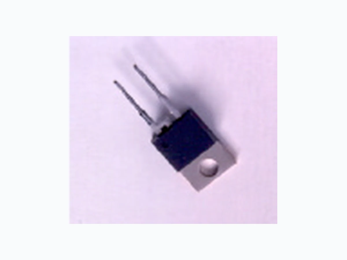
CSD01060 ETC1
Document overview
- Manufacturer or author: Provided By www.digicamel.com(FREE DATASHEET DOWNLOAD SITE)
- PDF pages: 5
Technical content
Page 1 • CSD01060, Rev - P O W E R ZERO RECOVERYTM RECTIFIER
- 600 Volt Schottky Rectifier • Replace Bipolar with Unipolar Rectifiers
- Zero Reverse Recovery • Essentially No Switching Losses
- Zero Forward Recovery • Higher Efficiency
- High Frequency Operation • Reduction Of Rectifier Heat Sink
- Temperature Independent Switching Behavior • Parallel Devices without Thermal Runaway
- Extremely Fast Switching
- Positive Temperature Coefficient on VF
- Switch Mode Power Supplies
- Power Factor Correction
- Motor Control Maximum Ratings Parameter Symbol Value Unit Repetitive Peak Reverse Voltage VRRM 600 V Surge Peak Reverse Voltage VRSM 600 V DC Blocking Voltage VDC 600 V Average Forward Current TC=150°C IF(AV) 1 A Repetitive Peak Forward Surge Current TC=25°C, tP=8.3ms, Half Sine Wave IFRM 5 A Non-Repetitive Peak Forward Surge Current TC=25°C, tp=10µs, Pulse IFSM 20 A Power Dissipation TC = 25°C Ptot 21.4 W Operating Junction and Storage Temperature TJ , Tstg -55 to +175 °C
Page 2 • CSD01060, Rev - P O W E R
ELECTRICAL CHARACTERISTICS
Parameter Symbol Min Typ Max Units Forward Voltage IF = 1A TJ=25°C IF = 1A TJ=150°C VF 1.6 2.0 1.8 2.4 V Reverse Current VR = 600V TJ=25°C VR = 600V TJ=150°C IR 100 500 µA Total Capacitive Charge VR = 600V,IF = 1A, di/dt = 500 A/µs, TJ = 25°C QC 3.3 nC Total Capacitance VR = 0V, TJ = 25 °C, f =1MHz VR = 200V, TJ = 25 °C, f =1MHz VR = 400V, TJ = 25 °C, f =1MHz C 8.5 pF NOTE: 1. This is a majority carrier diode, so there is no reverse recovery charge. THERMAL CHARACTERISTICS Characteristic Symbol Min Typ Max Units Thermal Resistance from Junction to Case Rθ JC 7 °C/W Thermal Resistance from Junction to Ambient Rθ JA 60 °C/W Typical Performance Figure 1. Forward Characteristics Figure 2. Reverse Characteristics
Figure 3. Current Derating Figure 4. Capacitance vs. Reverse Voltage
Page 4 • CSD01060, Rev - P O W E R Package Dimensions Package TO-220-2 Package TO-252-2 NOTE: 1. Dimension L, M, W apply for Solder Dip Finish. B A C D E F G H J K L N Min Max Min Max A .402 .408 10.211 10.364 B .120 .124 3.048 3.150 C .106 .110 2.692 2.794 D .245 .251 6.223 6.375 E .335 .345 8.509 8.763 F .149 .153 3.784 3.886 G .220 .240 5.588 6.096 H .540 .550 13.716 13.970 J K .080 2.032 L .050 .056 1.270 1.422 M .032 .038 .813 .956 N .197 .203 5.004 5.156 P .170 .180 4.318 4.572 Q .048 .052 1.219 1.321 R .583 .593 14.808 15.062 V .103 .107 2.616 2.718 W .015 .021 .381 .533 Y .396 .406 10.058 10.312 Inches MillimetersPOS .100 REF 2.540 REF PIN 1 PIN 2 CASE W V UT S R Q P Y X (2X) M A B C D E F G H J PIN 1 PIN 2 CASE K L M N P Q R S T U Min Max Min Max A .255 .265 6.477 6.731 B .197 .205 5.004 5.207 C .027 .033 .686 .838 D .292 .322 7.417 8.179 E .178 .182 4.521 4.623 F .025 .035 .635 .889 G 44° 46° 44° 46° H .382 .397 9.703 10.084 J K 6° 8° 6° 8° L .086 .094 2.184 2.388 M .030 .034 .762 .864 N .040 .044 1.016 1.118 P .235 .245 5.969 6.223 Q 0.00 .004 0.00 .102 R S .017 .023 .428 .588 T .040 .044 1.016 1.118 U .021 .027 .534 .686 R0.01TYP R0.31TYP POS Inches Millimeters .090TYP 2.286TYP
Page 5 • CSD01060, Rev - P O W E R Part Number Package Marking CSD01060A TO-220-2 SD01060 CSD01060E TO-252-2 SD01060 Cree, Inc. Power Products
4600 Silicon Drive
Durham, NC 27703 • USA tel: 919-313-5300 fax: 919-313-5451 www.cree.com Copyright © 2001 Cree, Inc. All rights reserved. Permission is given to reproduce this document provided the entire document (including this copyright notice) is duplicated. The information in this document is subject to change without notice. Cree and the Cree logo are trademarks of Cree, Inc.