
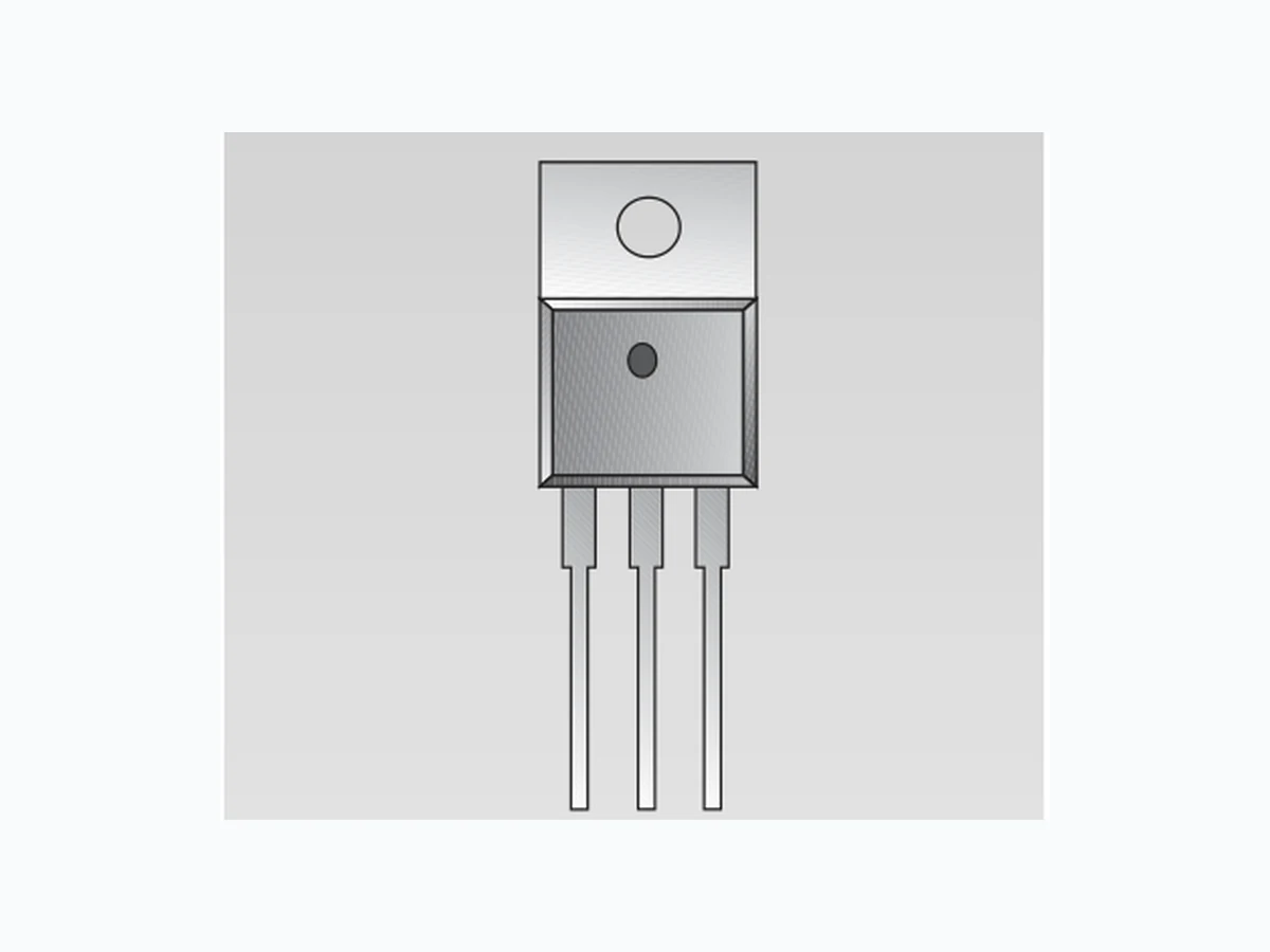
CS5210-1 CHERRY
Document overview
- Manufacturer or author: Provided By www.digicamel.com(FREE DATASHEET DOWNLOAD SITE)
- PDF pages: 8
Technical content
Features
3.3V@10A 300mFLoad200 124 0.1mF100mF 5.0V Adj VOUT n 1.25V to 4.5V VOUT at 10A n Dropout Voltage < 1.05V @ 10A n 2% Trimmed Reference n Fast Transient Response n Thermal Shutdown n Current Limit n Short Circuit Protection Package Options CS5210-1 10A LDO 3-Pin Adjustable Linear Regulator CS5210-1
Description
The CS5210-1 linear regulator pro- vides 10A at adjustable voltages from 1.25V to 4.5V. This adjustable device requires two external resis- tors to set the output voltage and provide the minimum load current for proper regulation. This regulator is intended for use as a post regulator and microprocessor supply. The fast loop response and low dropout voltage make this reg- ulator ideal for applications where low voltage operation and good transient response are important. The circuit is designed to operate with dropout voltages as low as 1.05V at 10A. The regulator is protected against overload conditions with overcur- rent and thermal shutdown protec- tion circuitry. The regulator is available in a TO-220 package. Applications Diagram
3 Lead TO-220
- Adjust 2. VOUT 3. VIN Tab = VOUT Cherry Semiconductor Corporation
2000 South County Trail, East Greenwich, RI 02818
Tel: (401)885-3600 Fax: (401)885-5786 Email: info@cherry-semi.com Web Site: www.cherry-semi.com A Company ¨ Rev. 6/12/97
Electrical Characteristics: 0¡C²TA ² 70¡C, 0¡C²TJ ² 150¡C, VAdj = 0V unless otherwise specified. PARAMETER TEST CONDITIONS MIN TYP MAX UNIT CS5210-1 Absolute Maximum Ratings Lead Temperature Soldering (-2%) (+2%) Line Regulation V IN=2.75V to 5.5V, IOUT=10mA .02 .20 % Load Regulation V IN=2.75V,IOUT=10mA to 10A .04 .50 % Minimum Load Current V IN=5V, ÆVOUT= +2% 5 10 mA (Note 1) Adjust Pin Current V IN=2.75V,IOUT=10mA 70 120 µA Current Limit V IN=2.75V,ÆVOUT= -2% 10.1 12.0 A Short Circuit Current V IN=2.75V,VOUT=0V 8.0 10.0 A Ripple Rejection V IN=3.25V Avg, 60 80 dB (Note 2) V Ripple=1VP-P @120Hz, IOUT=4A,CAdj=0.1µF, COUT=22µF Thermal Regulation 30ms Pulse, T A=25¡C 0.002 %/W (Note 2) Dropout Voltage I OUT=100mA 0.92 1.15 V (Minimum VIN -VOUT)I OUT=1A 0.93 1.15 V (Note 3) I OUT=2.75A 0.94 1.15 V IOUT=4A 0.95 1.15 V IOUT=10A 1.03 1.40 V RMS Output Noise Freq=10Hz to 10kHz, T A=25¡C 0.003 %V OUT Temperature Stability 0.5 % Thermal Shutdown 150 180 210 ¡C (Note 4) Thermal Shutdown Hysteresis 25 ¡C (Note 4) Note 1: The minimum load current is the minimum current required to maintain regulation. Normally the current in the resistor divider used to set the output voltage is selected to meet the minimum load current requirement. Note 2: This parameter is guaranteed by design and is not 100% production tested. Note 3: Dropout voltage is defined as the minimum input/output voltage differential required to maintain 2% regulation. Note 4: This parameter is guaranteed by design, but not parametrically tested in production. However, a 100% thermal shutdown f unctional test is performed on each part.
Typical Performance Characteristics Package Pin Description PACKAGE PIN # PIN SYMBOL FUNCTION 3L TO-220
1 Adjust This pin is connected to the low side of the internally trimmed
2% bandgap reference voltage and carries a bias current of about 70µA. A resistor divider from Adj to V OUT and from Adj to ground sets the output voltage. Also, transient response can be improved by adding a small bypass capacitor from this pin to ground. OUT This pin is connected to the emitter of the power pass transistor and provides a regulated voltage capable of sourcing 10A of current. IN This is the supply voltage for the regulator. For the device to regulate, this voltage should be between 1.2V and 1.40V (depending on the output current) greater than the output voltage. Block Diagram VIN BIAS and TSD VREF EA IA VOUT Adj + - 0.00 71.00 73.00Adjust Pin Current (uA) IOUT (A) 2.00 3.00 4.00 5.00 72.80 72.60 72.40 72.20 72.00 71.80 71.60 71.40 71.20 70.80 70.60 70.40 70.20 70.00 Adjust Pin Current vs IOUT 0 10 20 30 40 50 60 70 80 90 100 110120130 60.00 65.00 70.00 75.00 80.00 85.00 90.00 TCase (°C) ADJUST PIN CURRENT (mA) I0=10mA Adjust Pin Current Voltage vs Temperature
0 10 20 30 40 50 60 70 80 90 100 110120130 -0.150 -0.125 -0.100 -0.075 -0.050 -0.025 -0.000 0.025 0.050 0.075 0.100 TJ (°C) OUTPUT VOLTAGE DEVIATION (%) I0=10mA VIN=2.75V 0.000 0.050 0.150 0.200 0.300 OUTPUT CURRENT (A) OUTPUT VOLTAGE DEVIATION (%) 0.350 0.250 0.100 TCase=0°C TCase=25°C TCase=125°C Load Regulation vs Output CurrentReference Voltage vs Temperature CS5210-1 0 2.0 4.0 6.0 8.0 0.000 0.250 Output Current (A) VDROPOUT (mV) 0.500 0.750 1.000 1.250 0.0 0.5 5.5 0.0 20.0Output Current (A) VIN-VOUT (V) 18.0 16.0 14.0 12.0 10.0 8.0 6.0 4.0 2.0 Ilmin vs VIN - VOUT VDropout vs IOUT 1.00 0.80 1.00 Minimum Load Current (mA) VIN-VOUT (V) 2.00 3.00 4.00 5.00 0.98 0.96 0.94 0.92 0.90 0.88 0.86 0.84 0.82 TCASE =23˚C TCASE =125˚C TCASE =0˚C Minimum Load Current vs VIN-VOUT 10.0 101 Frequency (Hz) Ripple Rejection (dB) 20.0 30.0 40.00 60.0 70.0 80.0 90.0 102 103 104 106105 50.0 VIN-VOUT=2V IOUT=4A VRIPPLE=1VP-P COUT=22mF CADJ=0.1mF Ripple Rejection vs Frequency Typical Performance Characteristics: continued
Application Notes: continued The CS5210-1 linear regulator has a composite PNP-NPN output stage that requires an output capacitor for stability. A detailed procedure for selecting this capacitor is includ- ed in the Stability Considerations section. Design Guidelines This LDO adjustable regulator has an output voltage range of 1.25V to 4.5V. An external resistor divider sets the out- put voltage as shown in Figure 1. The regulatorÕs voltage sensing error amplifier maintains a fixed 1.25V reference between the output pin and the adjust pin. A resistor divider network R 1 and R2 causes a fixed current to flow to ground. This current creates a voltage across R2 that adds to the 1.25V across R1 and sets the overall output voltage. The adjust pin current (typically 50µA) also flows through R 2 and adds a small error that should be taken into account if precise adjustment of VOUT is necessary. The output voltage is set according to the formula: VOUT = VREF ´ + R2 ´ IAdj The term IAdj ´ R2 represents the error added by the adjust pin current. R1 is chosen so that the minimum load current is a least 10mA. R1 and R2 should be of the same composition for best tracking over temperature. The divider resistor should be placed as close to the IC as possible and connect- ed to the output with a separate metal trace.Figure 1: While not required, a bypass capacitor connected between the adjust pin and ground will improve transient response and ripple rejection. A 0.1µF tantalum capacitor is recom- mended for Òfirst cutÓ design. Value and type may be var- ied to optimize performance vs price. The CS5210-1 linear regulator has an absolute maximum specification of 6V for the voltage difference between V IN and VOUT. However, the IC may be used to regulate volt- ages in excess of 6V. The main considerations in such a design are power-up and short circuit capability. In most applications, ramp-up of the power supply to V IN is fairly slow, typically on the order of several tens of mil- liseconds, while the regulator responds in less than one microsecond. In this case, the linear regulator begins charging the output capacitor as soon as the V IN to VOUT differential is large enough that the pass transistor con- ducts current. V OUT is essentially at ground, and VIN is on the order of several hundred millivolts, so that the pass transistor is in dropout. As V IN increases, the pass transis- tor will remain in dropout, and current is passed to the load until V OUT is in regulation. Further increase in VIN brings the pass transistor out of dropout. The result is that the output voltage follows the power supply ramp-up, staying in dropout until the regulation point is reached. In this manner, any output voltage may be regulated. There is no theoretical limit to the regulated voltage as long as the V IN to VOUT differential of 6V is not exceeded. However, maximum ratings of the IC will be exceeded in a short circuit condition. Short circuit conditions will result in the immediate operation of the pass transistor outside of its safe operating area. Over-voltage stresses will then cause destruction of the pass transistor before overcurrent or thermal shutdown circuitry can become active. Additional circuitry may be required to clamp V IN to VOUT differential to less than 6V if failsafe operation is required. One possible clamp circuit is illustrated below; however, the design of clamp circuitry must be done on an applica- tion by application basis. Care must be taken to ensure the clamp actually protects the design. Components used in the clamp design must be able to withstand the short cir- cuit conditions indefinitely while protecting the IC. Figure 2: VIN VOUT VAdj EXTERNAL SUPPLY VIN CS5210-1 Adj VOUT R1 + R2 Adjustable Operation Theory of Operation
The output compensation capacitor helps determine three main characteristics of a linear regulator: start-up delay, load transient response, and loop stability. The capacitor value and type is based on cost, availability, size and temperature constraints. A tantalum or aluminum electrolytic capacitor is best, since a film or ceramic capaci- tor with almost zero ESR can cause instability. The alu- minum electrolytic capacitor is the least expensive solution. However, when the circuit operates at low temperatures, both the value and ESR of the capacitor will vary consider- ably. The capacitor manufacturerÕs data sheet provides this information. A 300µF tantalum capacitor will work for most applica- tions, but with high current regulators such as the CS5210 the transient response and stability improve with higher values of capacitance. The majority of applications for this regulator involve large changes in load current so the out- put capacitor must supply the instantaneous load current. The ESR of the output capacitor causes an immediate drop in output voltage given by: ÆV = ÆI ´ ESR. For microprocessor applications it is customary to use an output capacitor network consisting of several tantalum and ceramic capacitors in parallel. This reduces the overall ESR and reduces the instantaneous output voltage drop under transient load conditions. The output capacitor network should be as close to the load as possible for the best results. Protection Diodes When large external capacitors are used with a linear regu- lator it is sometimes necessary to add protection diodes. If the input voltage of the regulator gets shorted, the output capacitor will discharge into the output of the regulator. The discharge current depends on the value of the capaci- tor, the output voltage, and the rate at which V IN drops. In the CS5210-1 regulator, the discharge path is through a large junction and protection diodes are not usually need- ed. If the regulator is used with large values of output capacitance and the input voltage is instantaneously short- ed to ground, damage can occur. In this case, a diode con- nected as shown in Figure 3 is recommended. A rule of thumb useful in determining if a protection diode is required is to solve for current I= , where I is the current flow out of the load capacitance when V IN is shorted, C is the value of load capacitance V is the output voltage, and T is the time duration required for V IN to transition from high to being shorted. If the calculated current is greater than or equal to the typi- cal short circuit current valued provided in the specifica- tions, serious thought should be given to include a protec- tion diode. Figure 3: Current Limit The internal current limit circuit limits the output current under excessive load conditions and protects the regulator. Short Circuit Protection The device includes foldback short circuit current limit that clamps the output current at approximately two amperes less than its current limit value. Thermal Shutdown The thermal shutdown circuitry is guaranteed by design to become activated above a die junction temperature of 150¡C and to shut down the regulator output. This circuit- ry includes a thermal hysteresis circuit with 25¡C of typical hysteresis, thereby allowing the regulator to recover from a thermal fault automatically. Calculating Power Dissipation and Heat Sink Requirements High power regulators such as the CS5210-1 usually oper- ate at high junction temperatures. Therefore, it is important to calculate the power dissipation and junction tempera- tures accurately to ensure that an adequate heat sink is used. Since the package tab is connected to Vout on the CS5210-1, electrical isolation may be required for some applications. Also, as with all high power packages, ther- mal compound in necessary to ensure proper heat flow. For added safety, this high current LDO includes an inter- nal thermal shutdown circuit. The thermal characteristics of an IC depend on the follow- ing four factors. Junction temperature, ambient tempera- ture, die power dissipation, and the thermal resistance VIN CS5210-1 Adj VOUT C ´V T Stability Considerations Application Notes: continued
from the die junction to ambient air. The maximum junc- tion temperature can be determined by: TJ(max) = TA(max) + PD(max) ´ RQJA The maximum ambient temperature and the power dissi- pation are determined by the design while the maximum junction temperature and the thermal resistance depend on the manufacturer and the package type. The maximum power dissipation for a regulator is: P D(max) = (VIN(max) -VOUT(min))IOUT(max) + VIN(max) ´ IIN(max) A heat sink effectively increases the surface area of the package to improve the flow of heat away from the IC and into the surrounding air. Each material in the heat flow path between the IC and the outside environment has a thermal resistance which is measured in degrees per watt. Like series electrical resistances, these thermal resistances are summed to determine the total thermal resistance between the die junction and the surrounding air, R QJA. This total thermal resistance is comprised of three compo- nents. These resistive terms are measured from junction to case (R QJC), case to heat sink (RQCS), and heat sink to ambi- ent air (RQSA). The equation is: RQJA = RQJC + RQCS + RQSA RQJC is rated @ 1.4¡C/W for the CS5210-1. For a high cur- rent regulator such as the CS5210-1 the majority of heat is generated in the power transistor section. The value for R QSA depends on the heat sink type, while the RQCS depends on factors such as package type, heat sink inter- face (is an insulator and thermal grease used?), and the contact area between the heat sink and the package. Once these calculations are complete, the maximum permissible value of R QJA can be calculated and the proper heat sink selected. For further discussion on heat sink selection, see our Cherry application note ÒThermal Management for Linear Regulators.Ó CS5210-1 Application Notes: continued
8Rev. 6/12/97 © 1999 Cherry Semiconductor Corporation Thermal Data 3L TO-220 RQJC typ 1.4 ûC/W RQJA typ 50 ûC/W Package Specification PACKAGE DIMENSIONS IN mm (INCHES) Cherry Semiconductor Corporation reserves the right to make changes to the specifications without notice. Please contact Cherry Semiconductor Corporation for the latest available information. PACKAGE THERMAL DATA
Ordering Information
CS5210-1GT3 3L TO-220 Straight
3 Lead TO-220 (T) Straight
5.33 (.210) 4.83 (.190) 2.79 (.110) 2.29 (.090) 1.02 (.040) 0.63 (.025) 0.56 (.022) 0.38 (.014) 1.40 (.055) 1.14 (.045) 4.83 (.190) 4.06 (.160) 6.17 (.243) REF 1.14 (.045) 1.52 (.060) 1.14 (.045) 1.40 (.055) 2.87 (.113) 5.94 (.234) 14.22 (.560) 13.72 (.540) 2.92 (.115) 2.29 (.090) 9.78 (.385) 10.54 (.415) 3.71 (.146) 3.96 (.156) 14.99 (.590) 14.22 (.560)