
DATASHEET SEARCH SITE
Document overview
- Manufacturer or author: Provided By www.digicamel.com(FREE DATASHEET DOWNLOAD SITE)
- PDF pages: 2
Technical content
Features
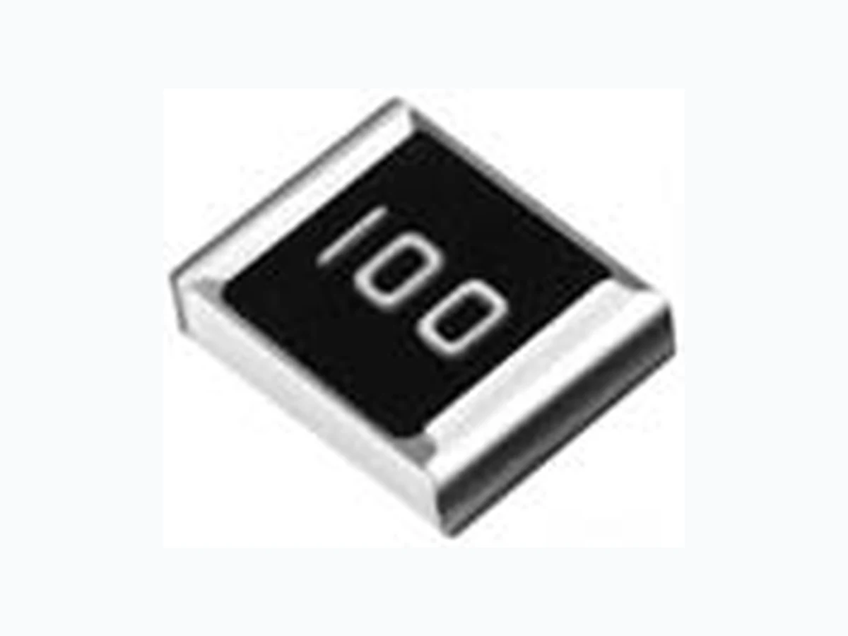
■ Special alloy resistor ■ Power rating at 70 °C: CRA2010 - 1 W, CRA2512 - 3 W ■ Inductance less than 5 nH ■ RoHS compliant* CRA2010/CRA2512 - High Power Current Sense Chip Resistor *RoHS Directive 2002/95/EC Jan. 27, 2003 including annex and RoHS Recast 2011/65/EU June 8, 2011. Specifi cations are subject to change without notice. The device characteristics and parameters in this data sheet can and do vary in different applications and actual device performance may vary over time. Users should verify actual device performance in their specifi c applications. Performance Characteristics *RoHS COMPLIANT DIMENSIONS: MM (INCHES)
Electrical Characteristics
Characteristic CRA2010 CRA2512 Power Rating @ 70 °C 1 W 3 W Operating Temperature Range -55 °C to +170 °C Derated to Zero Load at +170 °C Maximum Working Voltage (P x R) Insulation Resistance > 100 megohms Resistance Range 0.005 - 0.020 Ω 0.010 - 0.100 Ω Resistance Tolerance ±1 %, ±5 % Temperature Coeffi cient ±75 PPM/°C Product Dimensions Model A B C T Resistor Material Recommended Solder Pad Layout Test Conditions Specifi cation Thermal Shock -55 ˚C to + 150 ˚C, ΔR ±(0.5 % + 0.0005 Ω) 1000 Cycles, 15 minutes Short Time Overload 5 X Rated Power for 5 seconds ΔR ±(0.5 % + 0.0005 Ω) Low Temperature -55 ˚C for 24 hours ΔR ±(0.5 % + 0.0005 Ω) Storage High Temperature Exposure 1000 hours @ + 170 ˚C ΔR ±(1.0 % + 0.0005 Ω) Bias Humidity + 85 ˚C, 85 % RH, 10 % Bias, ΔR ±(0.5 % + 0.0005 Ω) 1000 hours Mechanical Shock 100 g’s for 6 milliseconds, 5 pulses ΔR ±(0.5 % + 0.0005 Ω) Vibration Frequency varied 10 to 2000 KHz ΔR ±(0.5% + 0.0005 Ω) in one minute, 3 directions, 12 hours Load Life 1000 hours at rated power at ΔR ±(1.0% + 0.0005 Ω) +70 ˚C, 1.5 hours on, 0.5 hours off Resistance to Solder +260 ˚C Solder, 10-12 second dwell, ΔR ±(0.5 % + 0.0005 Ω) Heat 25 mm/second emergence Moisture Resistance MIL-STD-202 Method 106, 0 % power ΔR ±(0.5% + 0.0005 Ω) (7a and 7b not required) A B SENSING TRACE Cu TRACE L Model A B L CRA2010 3.1 2.7 3.1 CRA2512 4.0 2.1 4.1 A B CC T CC Construction Overcoat Metal Alloy Plate Ni / Sn Plating DIMENSIONS: MM (INCHES) Model CRA2010 is currently available but not recommended for new designs.
CRA 2512 - F Z - R020 E LF Model (CRA = Precision Chip Resistor Size 2010 = 2010 Size 2512 = 2512 Size Resistance Tolerance
- F = ±1 %
- J = ±5 % TCR (PPM/°C)
- Z = ±75 PPM/°C Resistance Value “R” (decimal point) followed by three signifi cant digits (example: R025 = 0.025 ohm) Packaging
- E = 4000 pieces on 180 mm (7 inch) reel Termination
- LF = Tin-plated (RoHS compliant) Specifi cations are subject to change without notice. The device characteristics and parameters in this data sheet can and do vary in different applications and actual device performance may vary over time. Users should verify actual device performance in their specifi c applications. CRA2010/CRA2512 - High Power Current Sense Chip Resistor Packaging Dimensions (Conforms to EIA RS-481A) CRA2010 Resistance Values Available REV. 12/13 3.60 ± 0.20 (0.079 ± 0.002) 4.0 ± 0.05 (0.157 ± 0.004) 1.5 +0.1/-0 (0.059) DIA. MIN. 1.2 ± 0.15 (0.047 ± 0.006) 6.9 ± 0.2 (0.272 ± 0.008) 5.5 ± 0.05 (0.217 ± 0.002) 1.75 ± 0.1 (0.069 ± 0.004) 12.0 ± 0.2 (0.472 ± 0.008) TOP TAPE EMBOSSED TAPE RESISTOR USER DIRECTION OF FEED 60.0 (2.362) MIN. DIA. DIA. 180 +0/-3 (7.09 +0/-0.118) 13.0 ± 1.0 (0.512 ± 0.039) DIA. 15.4 ± 2.0 (0.606 ± 0.079) 13.0 ± 1.0 (0.512 ± 0.039) Code R Value Code R Value R005 0.005 R015 0.015 R010 0.010 R020 0.020 CRA2512 Resistance Values Available Code R Value Code R Value R010 0.010 R050 0.050 R015 0.015 R060 0.060 R020 0.020 R070 0.070 R025 0.025 R075 0.075 R030 0.030 R080 0.080 R040 0.040 R100 0.100 Consult factory for other resistance values. DIMENSIONS: MM (INCHES) 125 175 225 275 0 50 100 150 200 250 300 Time (seconds) Temperature (°C) 60 - 120 seconds 90 - 150 seconds 260 °C peak 190 °C 150 °C 220 °C Ramp Down 6 °C/second 255 °C Maximum of 20 seconds between +255 °C and +260 °C Ramp Up 3 °C/second maximum 10 seconds minimum <1> <1> Soldering Profi le Ambient Temperature (°C) 70 170 100 -55 Power Ratio (%) Derating Curve
Applications
■ Power supplies ■ Stepper motor drives