
 Download PDF
DATASHEET SEARCH SITE
Document overview
- PDF pages: 3
Technical content
Page 1
APPLICATIONS
FEATURES
- Measurement
- Single Output
- 20 Watts Output Power
- Wireless Network
- Telecom/Datacom
- High Efficiency up to 87%
- Industry Control System
- Fixed Switching Frequency
- Six-Sided Continuous Shield
- Semiconductor Equipment
- 2:1 and 4:1 Wide Input Voltage Range
- ISO9001 Certified Manufacturing Facilities
- Call Factory for More Output Power Options
- Compliant to RoHS EU Directive 2002/95/EC
- UL60950-1, EN60950-1, and IEC60950-1 Licensed
- CE Mark meets 2006/95/EC, 93/68/EEC, and 89/336 EEC
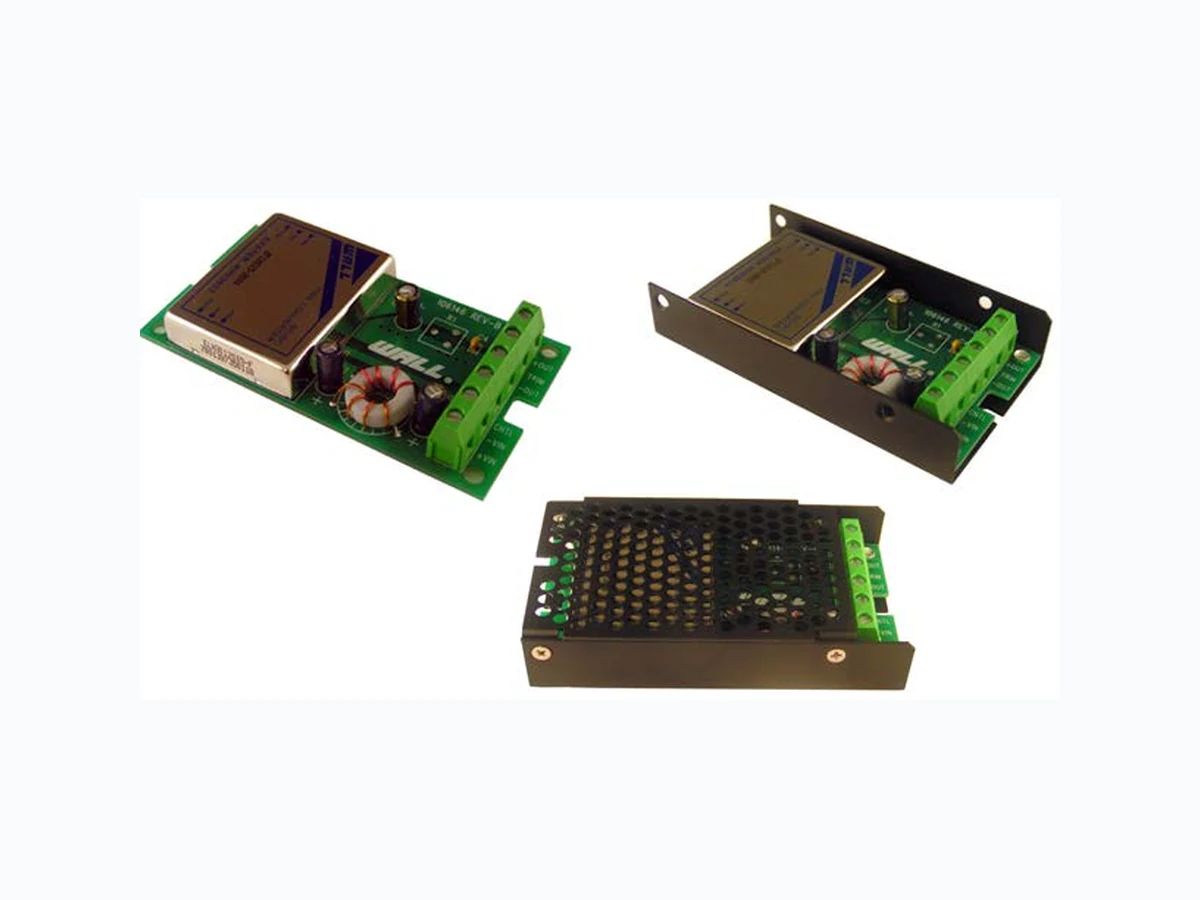
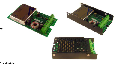
- Chassis Mount Options: Open Frame, U Channel, and Enclosed Types Available
SPECIFICATIONS: CMYF/YFW Series
All specifications apply @ 25°C ambient unless otherwise noted
INPUT SPECIFICATIONS
Input Voltage Range CMYF .............................12V nominal input ......................... 9-18VDC
24V nominal input ....................... 18-36VDC 48V nominal input ....................... 36-75VDC
CMYFW ..........................24V nominal input ......................... 9-36VDC
48V nominal input ....................... 18-75VDC
Input Surge Voltage (100ms max) ....... 12V input .......................... 36VDC
24V input .......................... 50VDC 48V input .........................100VDC
Input Reflected Ripple Current (nominal Vin and full load) ...........25mAp-p Start Up Time (nominal Vin and constant resistive load) ............. 20ms typ. Remote ON/OFF (See Note 7) (Positive Logic) ...............DC-DC ON ............ Open or 3.5V < Vr < 12V
DC-DC OFF ............ Short or 0V < Vr < 1.2V
Input Current of Remote Control Pin (nominal Vin) .......... -0.5mA ~ 1.0mA Remote Off State Input Current (nominal Vin) .................................. 20mA
OUTPUT SPECIFICATIONS
Output Voltage ............................................................................ see table Voltage Accuracy (nominal Vin and full load) ..................................... ±1% Voltage Adjustability ......................................................................... ±10% Output Current ............................................................................ see table Output Power ...................................................................... 20 watts max. Line Regulation (LL to HL at FL) ...................................................... ±0.2% Load Regulation (no load to full load) .............................................. ±0.5%
Minimum Load (See Note 6) ........................................................ see table Ripple/Noise (20 MHz BW) .......................................................... 75mVp-p Transient Response Recovery Time................................................ 250us (25% load step)
PROTECTION SPECIFICATIONS
Over Voltage Protection .......................... 3.3V Output ....................... 3.9V Zener diode clamp
5V Output .......................... 6.2V 12V Output ......................... 15V 15V Output ......................... 18V
Over Load Protection (% of full load at nominal input) ............. 150% max. Short Circuit Protection .................................. Hiccup, automatic recovery
GENERAL SPECIFICATIONS
Efficiency ..................................................................................... see table Switching Frequency ............................................................... 300KHz typ. Isolation Voltage (Input to Output) ........................................ 1600VDC min. Isolation Resistance ............................................................. 109 ohms min. Isolation Capacitance .............................................................. 300pF max.
ENVIRONMENTAL SPECIFICATIONS
Operating Temperature ................................-40°C to +85°C (with derating) Storage Temperature ......................................................... -55°C ~ +105°C Maximum Case Temperature .......................................................... +100°C Relative Humidity (non-condensing) .....................................5% to 95% RH Temperature Coefficient .................................................. ±0.02% / °C max. Thermal Impedance (See Note 8) Natural Convection ............................................................10°C / Watt Natural Convection with Heat-Sink ................................... 8.24°C/Watt Thermal Shock ................................................................... MIL-STD-810F
Vibration................................ 10~55Hz, 10G, 30 minutes along X, Y, and Z MTBF (See Note 1) ............................................................. 1.928 x 10⁶ hrs
PHYSICAL SPECIFICATIONS
Potting material of the DC/DC converter ........................... Epoxy (UL94-V0) Shielding of the DC/DC converter .............................................. six – sided Weight ........................................................................... Approximately 7oz Dimensions ..................................................4(L) x 2.2(W) x 0.81(H) inches
SAFETY & EMC
Approvals and Standards .................. IEC60950-1, UL60950-1, EN60950-1 EMI ................................... EN55022............................................. Class A
Air ± 8KV
ESD ........... EN61000-4-2……….. ………... Perf. Criteria B
Contact ± 6KV
Radiated Immunity ............. EN61000-4-3 ...............10V/m Perf. Criteria A Fast Transient .................... EN61000-4-4 ................ ±2KV Perf. Criteria B Surge ................................. EN61000-4-5 ................. .±1KV Perf. Criteria B Conducted Immunity .......... EN61000-4-6 ............ 10 Vrms Perf. Criteria A
Due to advances in technology, specifications subject to change without notice
Page 2
OUTPUT VOLTAGE / CURRENT RATING CHART
| Model Number | Input Range | Output Voltage | Output Current | Output (4) Ripple & Noise | Input Current | Eff. (4) | Capacitor(5) Load max | ||
|---|---|---|---|---|---|---|---|---|---|
| Min. load | Full load | No load (3) | Full load (2) | ||||||
| CMYF12S33-4000 | 9 - 18 VDC | 3.3 VDC | 280mA | 4000mA | 75mVp-p | 40mA | 1507mA | 77% | 13000uF |
| CMYF12S5-4000 | 5 VDC | 280mA | 4000mA | 75mVp-p | 15mA | 2193mA | 80% | 6800uF | |
| CMYF12S12-1600 | 12 VDC | 134mA | 1670mA | 75mVp-p | 40mA | 2110mA | 83% | 2200uF | |
| CMYF12S15-1330 | 15 VDC | 106mA | 1330mA | 75mVp-p | 20mA | 2083mA | 84% | 755uF | |
| CMYF(W)24S33-4000 | 18 - 36 VDC (9 - 36 VDC) | 3.3 VDC | 280mA | 4000mA | 75mVp-p | 10 (20)mA | 733 (764mA) | 79 (76) % | 13000uF |
| CMYF(W)24S5-4000 | 5 VDC | 280mA | 4000mA | 75mVp-p | 10 (10)mA | 1082 (1111mA) | 81 (79) % | 6800uF | |
| CMYF(W)24S12-1600 | 12 VDC | 134mA | 1670mA | 75mVp-p | 10 (20)mA | 1018 (1082mA) | 86 (81) % | 2200uF | |
| CMYF(W)24S15-1330 | 15 VDC | 106mA | 1330mA | 75mVp-p | 15 (20)mA | 1018 (1082mA) | 86 (81) % | 755uF | |
| CMYF(W)48S33-4000 | 36 - 75 VDC (18 - 75 VDC) | 3.3 VDC | 280mA | 4000mA | 75mVp-p | 10 (15)mA | 367 (377mA) | 79 (77) % | 13000uF |
| CMYF(W)48S5-4000 | 5 VDC | 280mA | 4000mA | 75mVp-p | 10 (10)mA | 543 (548mA) | 82 (80) % | 6800uF | |
| CMYF(W)48S12-1600 | 12 VDC | 134mA | 1670mA | 75mVp-p | 15 (10)mA | 509 (536mA) | 86 (82) % | 2200uF | |
| CMYF(W)48S15-1330 | 15 VDC | 106mA | 1330mA | 75mVp-p | 25 (10)mA | 506 (532mA) | 86 (82) % | 755uF | |
NOTES
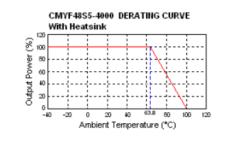
- BELLCORE TR-NWT-000332. Case I: 50% Stress, Temperature at 40ºC. (Ground fixed and controlled environment). 2. Maximum value at nominal input voltage and full load. 3. Typical value at nominal input voltage and no load. 4. Typical value at nominal input voltage and full load. 5. Test by minimum Vin and constant resistive load. 6. The output requires a minimum loading on the output to maintain specified regulation. Operation under no-load condition will not damage these devices, however they may not meet all listed specifications. 7. The ON/OFF control pin voltage is referenced to –Vin. 8. Heat sink is optional (for operation temperature range please see derating curve). Contact Factory for ordering details.
- The CMYF Series is 2:1 wide input range of 18-36VDC and 36-75VDC; the CMYFW Series is 4:1 ultra wide input range of 9-36VDC and 18-75VDC. 10. Chassis Mount Options: No suffix for open frame, “U” suffix for U Channel, and “E” suffix for Enclosed type.
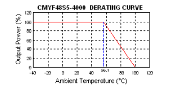
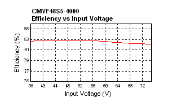
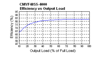
DERATING CURVES & EFFICIENCY GRAPHS
Page 3
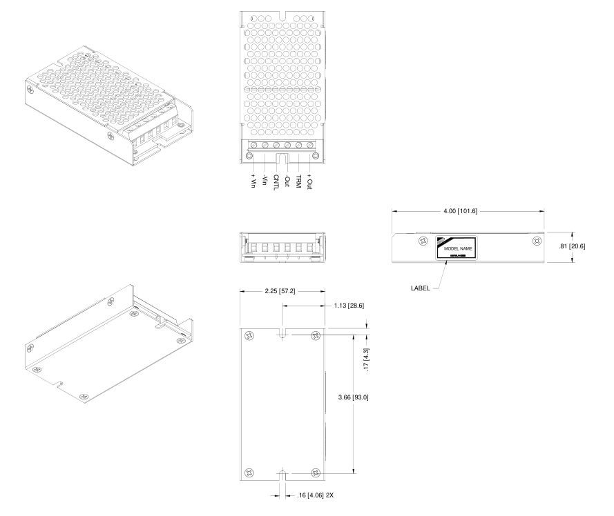
MECHANICAL DRAWING
Unit: inches [mm]