
 Download PDF
CMJR WALL
Document overview
- PDF pages: 3
Technical content
Page 1
FEATURES
- 10 Watts Output Power
- High Efficiency up to 86%
- Fixed Switching Frequency
- Six-Sided Continuous Shield
- 2:1 Wide Input Voltage Range
- International Safety Standard Approval
- Call Factory for More Output Power Options
- Options: Add suffix “-I” for Extended Operating Temperature Range
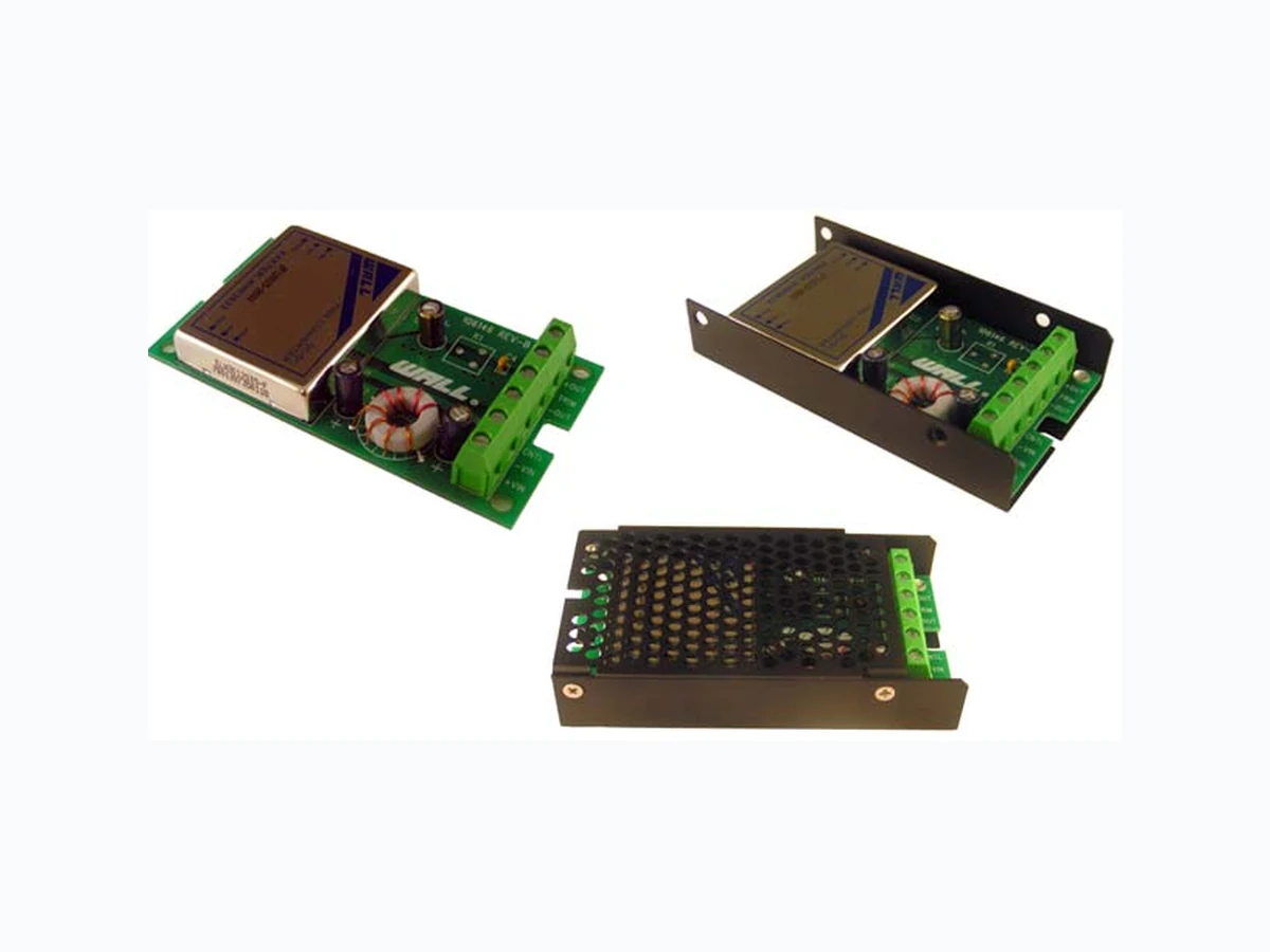
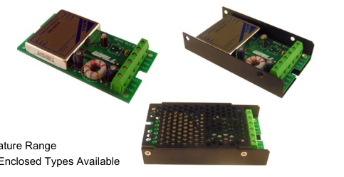
- Chassis Mount Options: Open Frame, U Channel, and Enclosed Types Available
SPECIFICATIONS: CMJR Series
All specifications apply @ 25°C ambient unless otherwise noted
INPUT SPECIFICATIONS
Input Voltage Range ............ 5V nominal input ......................... 4.5 - 9VDC
12V nominal input ........................ 9 - 18VDC 24V nominal input ...................... 18 - 36VDC 48V nominal input ...................... 36 - 75VDC
Input Surge Voltage (100ms max) ....... 5V input .............................15VDC
12V input ...........................36VDC 24V input ...........................50VDC 48V input .........................100VDC
Input Reflected Ripple Current......................................................30mAp-p (nominal Vin and full load)
Start Up Time (nominal Vin and constant resistive load).............20ms typ.
Remote ON/OFF (Option) (See Note 2) (Positive Logic)............... DC-DC ON.............Open or 3.5V < Vr < 12V
DC-DC OFF .............Short or 0V < Vr < 1.2V
(Negative Logic) ............. DC-DC ON...............Short or 0V < Vr < 1.2V
DC-DC OFF ...........Open or 3.5V < Vr < 12V
Remote Off Input Current (nominal Vin) ............................................20mA
OUTPUT SPECIFICATIONS
Output Voltage ..............................................................................see table
Voltage Accuracy (nominal Vin and full load) ...................................... ±1%
Output Current ..............................................................................see table
Output Power ........................................................................ 10 watts max.
Line Regulation (LL to HL at FL)....................................................... ±0.2%
Load Regulation (10% - 100 % FL).................................................. ±0.5%
Minimum Load (See Note 1) ..............................................10% of full load
Ripple/Noise (20 MHz BW)...........................................................50mVp-p
Temperature Coefficient ................................................. ±0.02% / °C max.
Transient Response Recovery Time (25% load step) .......................250us
PROTECTION SPECIFICATIONS
Over Voltage Protection................. 3.3V output ..................................3.9V (zener diode clamp)
5V output ..................................6.2V 12V output ...................................15V 15V output ...................................18V
Over Load Protection (% of full load at nominal input).............. 150% max.
Short Circuit Protection. ...................................Hiccup, automatic recovery
GENERAL SPECIFICATIONS
Efficiency ........................................................................................see table
Switching Frequency .................................................................300KHz typ.
Isolation Voltage (Input to Output).........................................1600VDC min. Isolation Resistance ...............................................................109 ohms min.
Isolation Capacitance ................................................................ 300pF max.
ENVIRONMENTAL SPECIFICATIONS
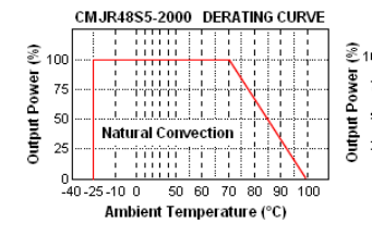
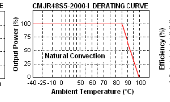
Operating Temperature (See derating curves) Standard ............................................... -25°C ~ +85°C (with derating) “I” (See Note 4)........................................ -40°C ~ +85°C (no derating)
(except for 5V input models)
Storage Temperature ..........................................................-55°C ~ +105°C
Maximum Case Temperature............................................................. 100°C
Relative Humidity...................................................................5% to 95% RH
Thermal Shock .................................................................... MIL-STD-810D
Vibration ................................10~55Hz, 10G, 30 minutes along X, Y, and Z MTBF (See Note 3) .......................................................... 1.976 x 10⁶ hours
PHYSICAL SPECIFICATIONS
Potting material of the DC/DC Converter ..........................Epoxy (UL94-V0)
Shielding of the DC/DC Converter.................................................. six-sided
Weight .............................................................................Approximately 6oz
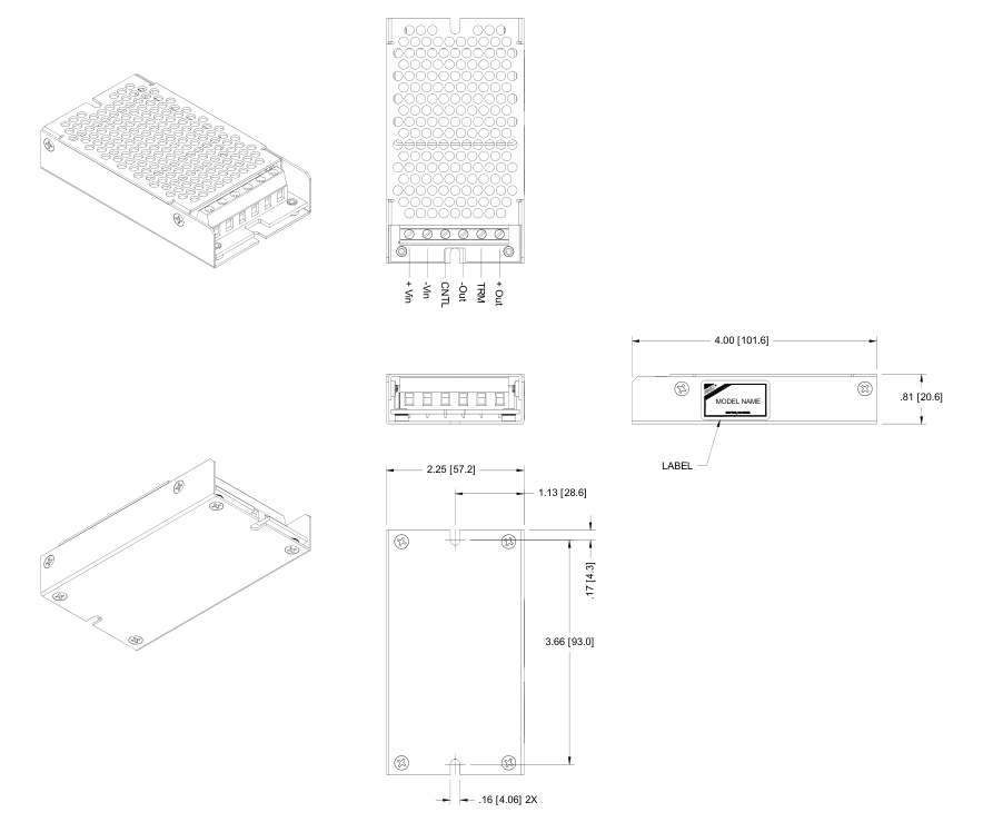
Dimensions............................................ 4.00(L) x 2.25(W) x 0.81(H) inches
SAFETY & EMC
Approvals and Standards .................. IEC60950-1, UL60950-1, EN60950-1
(except for 5V input models)
Conducted Emissions.........EN55022 ..............................................Class A
Radiated Emissions............EN55022 ..............................................Class A
EN55022 ..............................................Class B
ESD ....................................EN61000-4-2.............................Perf. Criteria B
Radiated Immunity..............EN61000-4-3.............................Perf. Criteria A
Fast Transient.....................EN61000-4-4.............................Perf. Criteria B
Surge..................................EN61000-4-5.............................Perf. Criteria B
Conducted Immunity...........EN61000-4-6.............................Perf. Criteria A
Due to advances in technology, specifications subject to change without notice
Page 2
OUTPUT VOLTAGE / CURRENT RATING CHART
| Model Number | Input Range | Output Voltage | Output Current | Output Ripple & Noise | Input Current (6) | Efficiency (7) | Capacitor(8) Load max |
|---|---|---|---|---|---|---|---|
| CMJR5S5-2000 | 5 VDC (4.5 – 9 VDC) | 5 VDC | 2000mA | 50mVp-p | 2500mA | 79% | 7900µF |
| CMJR5S12-830 | 12 VDC | 830mA | 50mVp-p | 2350mA | 82% | 2200µF | |
| CMJR5S15-660 | 15 VDC | 670mA | 50mVp-p | 2348mA | 82% | 1470µF | |
| CMJR12S33-2000 | 12 VDC (9 – 18 VDC) | 3.3 VDC | 2000mA | 50mVp-p | 724mA | 80% | 6800µF |
| CMJR12S5-2000 | 5 VDC | 2000mA | 50mVp-p | 1082mA | 81% | 4700µF | |
| CMJR12S12-830 | 12 VDC | 830mA | 50mVp-p | 1037mA | 84% | 690µF | |
| CMJR12S15-660 | 15 VDC | 670mA | 50mVp-p | 1046mA | 84% | 470µF | |
| CMJR24S33-2000 | 24 VDC (18 – 36 VDC) | 3.3 VDC | 2000mA | 50mVp-p | 362mA | 80% | 6800µF |
| CMJR24S5-2000 | 5 VDC | 2000mA | 50mVp-p | 534mA | 82% | 4700µF | |
| CMJR24S12-830 | 12 VDC | 830mA | 50mVp-p | 519mA | 84% | 690µF | |
| CMJR24S15-660 | 15 VDC | 670mA | 50mVp-p | 523mA | 84% | 470µF | |
| CMJR48S33-2000 | 48 VDC (36 – 75 VDC) | 3.3 VDC | 2000mA | 50mVp-p | 181mA | 80% | 6800µF |
| CMJR48S5-2000 | 5 VDC | 2000mA | 50mVp-p | 260mA | 84% | 4700µF | |
| CMJR48S12-830 | 12 VDC | 830mA | 50mVp-p | 253mA | 86% | 690µF | |
| CMJR48S15-660 | 15 VDC | 670mA | 50mVp-p | 252mA | 87% | 470µF |
NOTES
- The CMJR Series requires a minimum 10% loading on the output to maintain specified regulation. Operation under no load condition will not damage these devices, however, they may not meet all listed specifications.
- The ON/OFF control pin voltage is referenced to –Vin. To order negative logic On/Off control add the suffix “-R” (Ex: CMJR5S5-2000-R).
- BELLCORE TR-NWT-000332. Case 1: 50% Stress, Temperature at 40ºC. (Ground fixed and controlled environment).
- “I” Version is more efficient; therefore, it can be operated over a more extensive temperature range than the standard version. Please add the suffix “-I” for industrial grade temperature range models.
- Heat sink is optional, please consult factory for ordering details.
- Maximum value at nominal input voltage and full load of standard type.
- Typical value at nominal input voltage and no load.
- Tested at minimum Vin and constant resistive load.
- Chassis Mount Options: No suffix for open frame, “U” suffix for U Channel, and “E” suffix for Enclosed type.
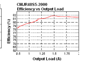
DERATING CURVES
Page 3
MECHANICAL DRAWING
Unit: inches [mm]