
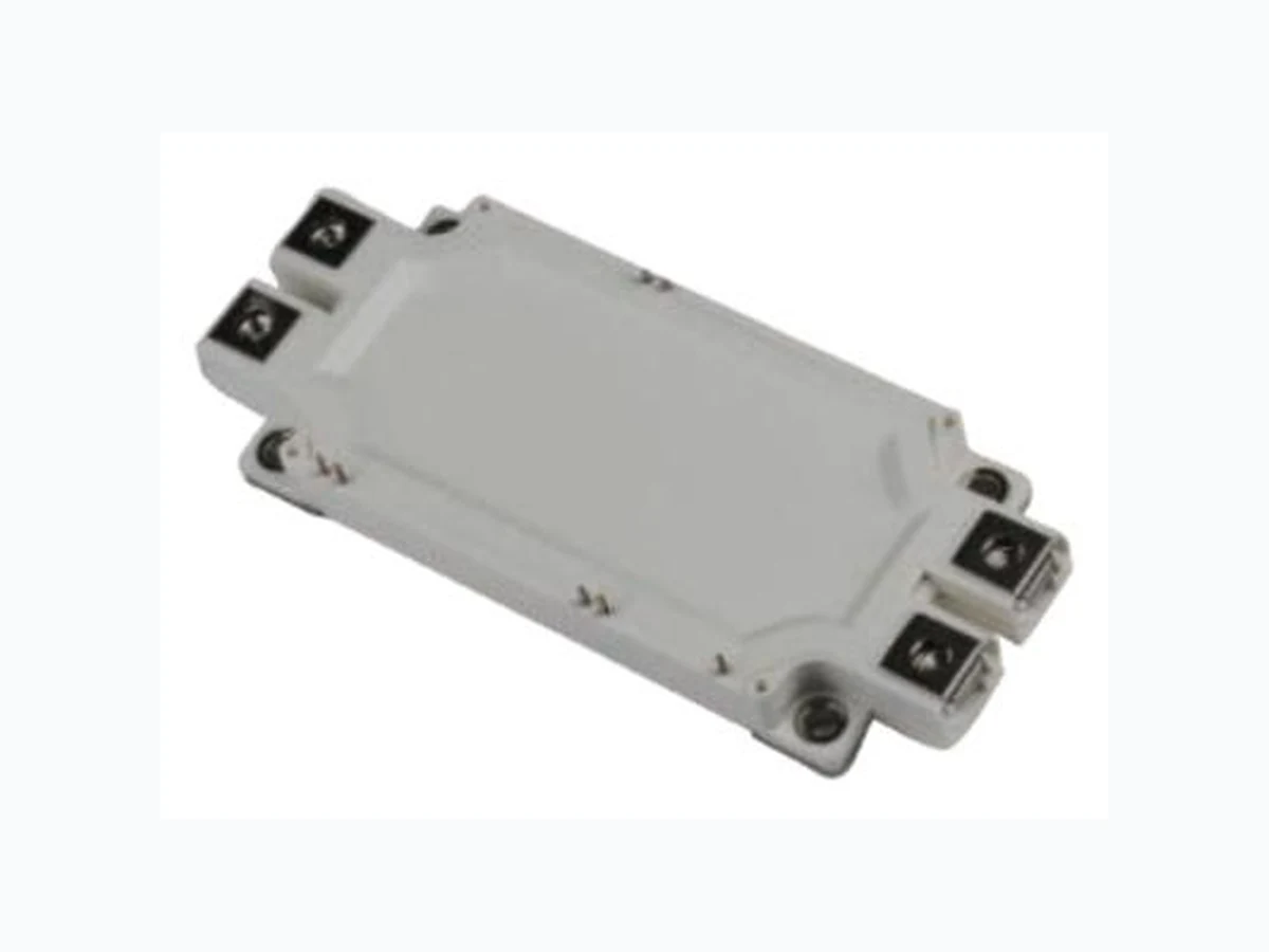
CM450DX-24S ISC
Document overview
- Manufacturer or author: Provided By www.digicamel.com(free datasheet download site)
- PDF pages: 6
Technical content
www.iscsemi.com 1
FEATURES
- HighSpeedSwitching
- LowPower Loss
APPLICATIONS
- Highpowerconverters
- Motordrives
- UPSsystems
- Windturbines IGBT,INVERTERMAXIMUM RATEDVALUES(TC=25℃ UNLESS OTHERWISESPECIFIED) SYMBOL PARAMETER VALUE UNIT VCES Collector-EmitterVoltage 1200 V VGES Gate-EmitterVoltage ±20 V IC CollectorCurrent-Continuous @TC=119℃ 450 A ICM PulsedCollectorCurrent 900 A PD PowerDissipation , TC=25℃ 3405 W IE Emittercurrent 450 A IERM PulsedEmittercurrent 900 A Viso IsolationVoltage(AllTerminalsShorted) 2500 V TJOP OperatingJunctionTemperatureRange –40~+150 ℃ Tstg Storagetemperature –40~+125 ℃
www.iscsemi.com 2 ELECTRICALCHARACTERISTICS(TC=25℃ UNLESSOTHERWISESPECIFIED) SYMBOL PARAMETER CONDITIONS MIN TYP MAX UNIT VCES Collector-EmitterBreakdownVoltage VGE=0;IC=1mA 1200 -- -- V VGE(TH) Gate-EmitterThresholdVoltage VGE=10V;IC=45mA 5.4 6.6 V VCE(sat) Collector-EmitterSaturationVoltage IC=450A;VCE=15V, TC=25℃ -- 2.15 V VCE(sat) Collector-EmitterSaturationVoltage IC=450A;VCE=15V, ICES ZeroGateVoltageCollectorCurrent VCE=1200V;VGE=0 -- -- 1.0 mA IGES Gate-EmitterLeakageCurrent VGE=±20V;VCE=0 -- -- 0.5 uA Cies InputCapacitance VGS =0V, VCS =210V, f=1.0MHz -- -- 45 nFCOes Outputcapacitance -- -- 9.0 Cres ReverseTransferCapacitance -- -- 0.75 QG GateCharge VCE =600V,IC =450A, VGE =15V -- 1050 -- uC
www.iscsemi.com 3 SWITCHINGCHARACTERISTICS(TC=25℃ UNLESSOTHERWISESPECIFIED) SYMBOL PARAMETER CONDITIONS MIN TYP MAX UNIT td(on) Turn-onDelayTime VGE = ±15V, IC=450A, VCE =600V, RG=0Ω -- -- 800 ns tr Turn-onRiseTime -- -- 200 td(off) Turn-offDelayTime -- -- 600 tf Turn-offFallTime -- -- 300 Qrr Reverserecoverycharge -- 24 -- µC trr Reverserecoverytime -- -- 300 ns Eon Turn-onswitchingenergyperpulse VGE = ±15V, IC=450A, VCE =600V, RG=0Ω, Tj=150 ℃, -- 54.9 -- mJ Eoff Turn-offswitchingenergyperpulse -- 48.0 -- mJ Err Reverserecoveryenergyperpulse -- 32.4 -- mJ RCC'+EE' Internalleadresistance Mainterminals-chip, perswitch -- -- 0.7 mΩ rg Internalgateresistance Perswitch -- 4.3 -- Ω THERMALRESISTANCECHARACTERISTICS SYMBOL PARAMETER CONDITIONS MIN TYP MAX UNIT Rth(j-c)Q Thermalresistance Junctiontocase,perInverter IGBT -- 44 K/kW Rth(j-c)D Junctiontocase,perInverter DIODE 78 Rth(c-s) Contactthermalresistance Casetoheatsink,per1 module,Thermalgrease applied
www.iscsemi.com 4 MECHANICALCHARACTERISTICS Mt MainterminalM6 1.96 -- 2.94 N.m Ms MountingholesM5 1.96 -- 2.94 N.m m mass -- 500 -- g ds Creepagedistance Terminaltoterminal 11.26 mm Terminaltobaseplate 12.46 da Clearance Terminaltoterminal 10 mm Terminaltobaseplate 10.12 ec Flatnessofbaseplate OnthecenterlineX,Y 0 100 μm INTERNALNTC-THERMISTORCHARACTERISTICS SYMBOL PARAMETER CONDITIONS MIN TYP MAX UNIT R25 RatedResistance TNTC=25℃ -- 5.0 -- KΩ △R/R DeviationofR100 TJ =100℃,R100=493Ω -7.3 -- +7.8 % P25 PowerDissipation TNTC=25℃ -- -- 10 mW B25/50 B-Value R2 = R25 exp [B25/50(1/T2 -
www.iscsemi.com 5 INTERNALCONNECTION: PACKAGEOUTLINE (UNIT:MM):
www.iscsemi.com 6 PRODUCTDISCLAIMER ISCreserves the rights tomakechangesof thecontent hereinthe datasheetatany timewithout notification.The informationcontained hereinis presentedonly as aguidefortheapplications ofour products. ISCproducts are intendedforusagein generalelectronic equipment.Theproducts are notdesigned for usein equipmentwhichrequire specialized qualityand/or reliability,orin equipment whichcould have applications inhazardous environments,aerospaceindustry,or medicalfield.Pleasecontactusif you intend ourproducts tobe used inthese specialapplications. ISCmakes nowarranty orguarantee regardingthe suitabilityof its products foranyparticularpurpose, nordoes ISCassumeanyliability arisingfrom theapplication oruse ofanyproducts, and specifically disclaimsany and allliability,includingwithout limitation special,consequential orincidental damages.