
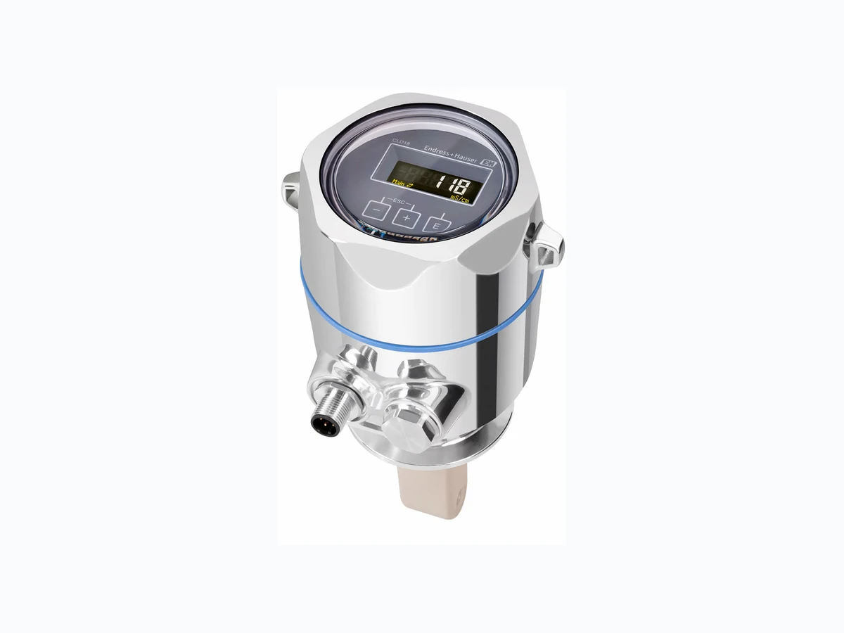
CLD18 EH
Document overview
- Manufacturer or author: Provided By www.digicamel.com(free datasheet download site)
- PDF pages: 16
Technical content
Compact measuring system for inductive conductivity measurement in liquids with medium to high conductivity. The structure is made from highly durable, food-safe polyetheretherketone (PEEK). The excellent chemical resistance properties of the sensor mean it can also be used in applications outside the food industry. The measuring system is perfectly suited for:
- Phase separation of product/water mixtures in the beverage industry
- Control of cleaning-in-place facilities (CIP), concentration control, separation in the cleaning return line
- Industrial water monitoring
- Rinsing processes in pickling plants Your benefits
- Hygienic sensor design in accordance with EHEDG and 3-A requirements, no risk of recontamination
- Stainless steel or plastic transmitter housing, IP 69, can be cleaned with high- pressure steam
- High level of repeatability, 0.5 % of reading, always guarantees same separation or monitoring
- Optionally available with IO-Link Products Solutions Services Technical Information Smartec CLD18 Compact inductive conductivity measurement for the food and beverage industry TI01080C/07/EN/06.21 71530811 2021-06-30
2 Endress+Hauser
Function and system design Measuring principle Inductive conductivity measurement An oscillator (1) generates an alternating magnetic field in the primary coil (2), which induces a current flow (3) in the medium. The strength of the current depends on the conductivity and thus on the ion concentration in the medium. The current flow in the medium, in turn, generates a magnetic field in the secondary coil (4). The resulting induced current is measured by the receiver (5) and used to determine the conductivity. 1 5 A0004894 1 Inductive conductivity measurement
1 Oscillator
2 Primary coil
3 Current flow in the medium
4 Secondary coil
5 Receiver
Advantages of inductive conductivity measurement:
- No electrodes and therefore no polarization effects
- Accurate measurement in media with a high degree of pollution and a tendency to form buildup
- Complete galvanic isolation of the measurement and the medium Input Measured variables Conductivity Temperature Measuring range Conductivity: Recommended range: 200 μS/cm to 1000 mS/cm (uncompensated) Temperature: –10 to 130 °C (14 to 266 °F)
Binary input The binary input is used in the SIO 1) (without IO-Link communication) for measuring range switching. Voltage range 0 V to 30 V High voltage min. Analog: 12.0 V IO-Link: 13.0 V Low voltage max. Analog: 9.0 V IO-Link: 8.0 V Current consumption at 24 V Analog: 30.0 mA IO-Link: 5.0 mA Undefined voltage range Analog: 9.0 to 12.0 V IO-Link: 8.0 to 13.0 V Output Output signal Conductivity: Analog: 0 / 4 to 20 mA, galvanically isolated IO-Link: 0 / 4 to 20 mA Temperature: Analog: 0 / 4 to 20 mA, galvanically isolated Load Max. 500 Ω Characteristic Linear Signal resolution Resolution: > 13 bit Accuracy: ± 20 μA Alarm output (only CLD18- A/B/C/D) The alarm output is implemented as an "open collector". Max. current 200 mA Max. voltage 30 V DC Error or device without supply voltage Alarm output blocked (0 mA) No error Alarm output open (up to 200 mA) Protocol-specific data (only CLD18-E) IO-Link specification Version 1.1.3 Device ID 0x020101 (131329) Manufacturer ID 0x0011 (17) IO-Link Smart Sensor Profile 2nd Edition Identification, diagnosis, DMSS (digital measuring and switching sensors) SIO mode Yes Velocity COM2 (38.4 kBd) Minimum cycle time 10 ms Process data width: 80 bit IO-Link data storage Yes Block configuration Yes 1) SIO = standard input output
4 Endress+Hauser
Terminal assignment (only CLD18-A/B/C/D) -+ LLL+ L- Out+Out-MRS+MRS-I ut1-O I ut2+OI ut1+O I ut2-O X A0029684 2 Terminal assignment IOut1 Current output conductivity (active) IOut2 Current output temperature (active) Out Alarm output (open-collector) MRS Binary input (measuring range switch) L+/L- Power supply X Grounding pin (flat male tab 4.8 mm)
1 Cover on electronics box
2 Electronics box
Supply voltage Analog: 24 V DC ± 20 %, protected against reverse polarity IO-Link: 18 to 30 V DC (SELV, PELV, Class 2), protected against reverse polarity Power consumption Analog: 3 W IO-Link: 1 W
X I ut1O I ut2O L MRS Alarm Out A0033106 3 Electrical connection CLD18-E (with IO-Link) BN WH BK BU OUT2 OUT1 A0045775 4 Connection via M12 connector (A-coded) 1 L+
2 OUT2, current output 0/4 to 20 mA
4 OUT1, IO-Link communication / SIO input for measuring range switching
Cable specification Analog: 0.5 mm2 recommended, max. 1.0 mm2 IO-Link: 0.34 mm2 recommended, maximum cable length 20 m Overvoltage protection Overvoltage category I Performance characteristics Response time Conductivity: t95 < 1.5 s Temperature: t90 < 20 s Measured error Conductivity: ± (2.0 % of measured value + 20 µS/cm) Temperature: ± 1.5 K Signal outputs ± 50 μA
6 Endress+Hauser
Repeatability Conductivity: max. 0.5 % of measured value ± 5 µS/cm ± 2 digits Cell constant 11.0 cm-1 Temperature compensation Range –10 to 130 °C (14 to 266 °F) Types of compensation • None
- Linear with user-configurable temperature coefficient Reference temperature 25 °C (77 °F) Installation Mounting instructions Hygienic requirements ‣ Easily cleanable installation of equipment according to the criteria of the EHEDG must be free of dead legs. ‣ If a dead leg is unavoidable, it shall be kept as short as possible. Under no circumstances shall the length of a dead leg L exceed the pipe’s inner diameter D minus the equipment’s enveloping diameter d. The condition L ≤ D – d applies. ‣ Furthermore, the dead leg must be self-draining, so neither product nor process fluids are retained therein. ‣ Within tank installations, the cleaning device must be located so that it directly flushes the dead leg. ‣ For further reference, see the recommendations concerning hygienic seals and installations in EHEDG Doc. 10 and the Position Paper: “Easy cleanable Pipe couplings and Process connections”. For 3-A-compliant installation, please observe the following: ‣ After the device has been mounted, hygienic integrity must be guaranteed. ‣ The leakage hole must be located at the lowest point on the device. ‣ 3-A-compliant process connections must be used. Orientations The sensor must be completely immersed in the medium. Avoid air bubbles in the area of the sensor. > 1 (3.3) A0037970 5 Orientation of conductivity sensors. Engineering unit: m (ft) Changes in the flow direction (after pipe bends) can cause turbulence in the medium. 1. Install the sensor at a distance of at least 1 m (3.3 ft) downstream from a pipe bend. 2. When installing, align the sensor in such a way that the medium flows through the flow opening of the sensor in the direction of medium flow. The sensor head must be completely immersed in the medium.
In confined installation conditions, the walls affect the ionic current in the liquid. This effect is offset by what is referred to as the installation factor. The installation factor can be entered in the transmitter for the measurement or the cell constant is corrected by multiplying by the installation factor. The value of the installation factor depends on the diameter and the conductivity of the pipe nozzle as well as the distance a between the sensor and the wall. The installation factor can be disregarded (f = 1.00) if the distance to the wall is sufficient (a > 20 mm, from DN 60). If the distance to the wall is shorter, the installation factor increases for electrically insulating pipes (f > 1) and decreases for electrically conductive pipes (f < 1). It can be measured using calibration solutions, or a close approximation can be determined from the following diagram. a A0037972 6 CLD18 installation a Wall distance a [inch] 0 10 20 30 40 a [mm] 0.95 1 00 . 1.05 f 0.39 0.79 1.18 1.57 A0020517 7 Relationship between installation factor f and wall distance a
1 Electrically conductive pipe wall
2 Electrically insulating pipe wall
‣ Install the measuring system in such a way that the housing is not exposed to direct sunlight. Environment Ambient temperature Stainless steel process connection: –20 to 60 °C (–4 to 140 °F) PVC process connection: –10 to 60 °C (14 to 60 °F) Storage temperature Stainless steel process connection: –25 to 80 °C (–13 to 176 °F) PVC process connection: –10 to 60 °C (14 to 140 °F) Humidity ≤ 100 %, condensating Climate class Climate class 4K4H as per EN 60721-3-4 Degree of protection IP 69 as per EN 40050:1993 Degree of protection NEMA TYPE 6P as per NEMA 250-2008 Shock resistance Complies with IEC 61298-3, certified up to 50 g Vibration resistance Complies with IEC 61298-3, certified up to 5 g
8 Endress+Hauser
Analog: Interference emission as per EN 61000-6-3:2007 + A1:2011 and EN 55011:2009 + A1:2010 Interference immunity as per EN 61326-1:2013 IO-Link: Interference emission according to EN 61326-1:2013, Class A Interference immunity according to EN 61326-1:2013, Class A and IEC 61131-9:2013 (at least: Annex G1) Pollution degree Pollution level 2 Altitude <2000 m (6500 ft) Process Process temperature Stainless steel process connection: –10 to 110 °C (14 to 230 °F) Max.130 °C (266 °F) up to 60 minutes PVC process connection: –10 to 60 °C (14 to 140 °F) Absolute process pressure Stainless steel process connection: 13 bar (188.5 psi), abs to up to 50 °C (122 °F) 7.75 bar (112 psi), abs at 110 °C (230 °F) 6.0 bar (87 psi), abs at 130 °C (266 °F) max. 60 minutes 1 to 6 bar (14.5 to 87 psi), abs in CRN environment tested with 50 bar (725 psi) PVC process connection: 9 bar (130.5 psi), abs to up to 50 °C (122 °F) 6.0 bar (87 psi), abs at 60 °C (140 °F) 1 to 6 bar (14.5 to 87 psi), abs in CRN environment tested with 50 bar (725 psi) Pressure-temperature ratings p (abs.) T [bar] [°C] 130110 [psi] 188.5 T[°F]230 266 122 A 140 9130.5 114.5 A0045788 8 Pressure/temperature ratings
1 Stainless steel process connection
2 PVC process connection
A Process temperature increased briefly (max. 60 minutes) Flow velocity max. 10 m/s (32.8 ft/s) for low-viscosity media in pipe DN 50
Design and dimensions CLD18-A/B/C/D (without IO-Link) 28 (1.10) 73.5 (0.91) 86 (3.39) 136.5 (5.37) 101.7 (4.00) 28 (1.10) 78 (3.07) 85 (3.35) 653.3(2.10) 127 (5.00) 85 (3.35) 114.5 (4.51) 53.3(2.10)69(2.72) 5.2 20.5 (0.81) 123 (4.84) A A B B C D (0.24) (2.89) (0.20) A0018942 9 Dimensions and versions (examples). Engineering unit: mm (in) A Plastic housing with thread G 1½ B Stainless steel housing with ISO 2852 clamp 2" C Stainless steel housing with Varivent DN 40 to 125 D Plastic housing with coupling nut 2¼" PVC
10 Endress+Hauser
CLD18-E (with IO-Link) 28 (1.10) 73.5 85 (3.35) 114.5 (4.51) 53.3(2.10)69(2.72) 5.2 20.5 (0.81) 123 (4.84) A A B (2.89) (0.20) A0045771 10 Dimensions and versions (examples). Engineering unit: mm (in) A Stainless steel housing with ISO 2852 clamp 2" B Stainless steel housing with Varivent DN 40 to 125 Weight Stainless steel housing: max. 1.870 kg (4.12 lbs) Plastic housing: max. 1.070 kg (2.36 lbs) Materials In contact with medium Sensor: PEEK (polyetheretherketone) Process connection: Stainless steel 1.4435 (AISI 316 L), PVC-U Seal: EPDM Not in contact with medium Stainless steel housing: Stainless steel 1.4308 (ASTM CF-8, AISI 304) Plastic housing: PBT GF20, PBT GF10 Seals: EPDM Window: PC Cable glands: PA, TPE
53.3(2.10) (2.72)69 53.3(2.10) (2.72)69 53.3(2.10) (2.72)69 GGE / GCP MDK MEK MOK MQK MXK MYK TXJ TDK 17.1(0.67) (1.29)32.8 TSK LQP Ø 39.7 (1.56) 7 (0.28) 32.7(1.29) 86 (3.39) 101.7 (4.00) Ø 84 (3.31) Ø 83 (3.27) A0018955 11 Process connections, dimensions in mm (inch) GGE GCP MDK MEK MOK MQK MXK MYK TXJ TDK TSK LQP Thread G1½ Thread G1½ PVC Aseptic DIN 11864-1-A DN 50 Aseptic DIN 11864-1-A DN 40 Dairy fitting DIN 11851 DN 50 Dairy fitting DIN 11851 DN 40 Dairy fitting DIN 11853 -2 DN 40 Dairy fitting DIN 11853 -2 DN 50 SMS 2" Tri-Clamp ISO 2852 2" Varivent N DN 40 to 125 Coupling nut 2¼" PVC Temperature sensor Pt1000
12 Endress+Hauser
Local operation can be locked and unlocked via IO-Link. E+_ ESC- - Main µS/cm A0018963 12 Local display and buttons
1 Parameter
2 Measured value
3 Unit
4 Operating keys
In the event of an error the device automatically alternates between displaying the error and the measured value. The operating language is English. System integration IO-Link In order to integrate field devices into a digital communication system, the IO-Link system needs a description of the device parameters, such as output data, input data, data format, data volume and supported transfer rate. This data is available in the IODD (IO Device Description) which is provided to the IO-Link master via generic modules when the communication system is commissioned. Download via endress.com 1. endress.com/download 2. Select Device Driver from the search options shown. 3. For Type select "IO Device Description (IODD)". 4. Select the Product Code or enter it as text. A list of search results is displayed. 5. Download the appropriate version. Download via ioddfinder 1. ioddfinder.io-link.com 2. For Manufacturer select "Endress+Hauser". 3. Enter the Product Name. A list of search results is displayed. 4. Download the appropriate version.
Certificates and approvals Current certificates and approvals for the product are available via the Product Configurator at www.endress.com. 1. Select the product using the filters and search field. 2. Open the product page. The Configuration button opens the Product Configurator.
Ordering information
Product page www.endress.com/CLD18 Product Configurator On the product page there is a Configure button to the right of the product image. 1. Click this button. The Configurator opens in a separate window. 2. Select all the options to configure the device in line with your requirements. In this way, you receive a valid and complete order code for the device. 3. Export the order code as a PDF or Excel file. To do so, click the appropriate button on the right above the selection window. For many products you also have the option of downloading CAD or 2D drawings of the selected product version. Click the CAD tab for this and select the desired file type using picklists. Scope of delivery The scope of delivery comprises:
- Smartec CLD18 measuring system in the version ordered
- Analog: Operating Instructions BA01149C
- IO-Link: Operating Instructions BA02097C Accessories The following are the most important accessories available at the time this documentation was issued. ‣ For accessories not listed here, please contact your Service or Sales Center. Standard solutions Conductivity calibration solutions CLY11 Precision solutions referenced to SRM (Standard Reference Material) by NIST for qualified calibration of conductivity measuring systems in accordance with ISO 9000:
- CLY11-C, 1.406 mS/cm (reference temperature 25 °C (77 °F)), 500 ml (16.9 fl.oz) Order No. 50081904
- CLY11-D, 12.64 mS/cm (reference temperature 25 °C (77 °F)), 500 ml (16.9 fl.oz) Order No. 50081905
- CLY11-E, 107.00 mS/cm (reference temperature 25 °C (77 °F)), 500 ml (16.9 fl.oz) Order No. 50081906 For further information on "Calibration solutions", see the Technical Information → 2
www.addresses.endress.com *71530811* 71530811