

 Download PDF
DATASHEET SEARCH SITE
Document overview
- PDF pages: 4
Technical content
Page 1
®
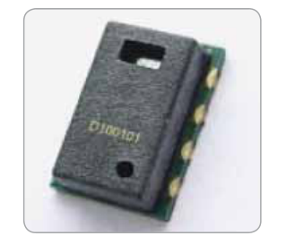
ChipCap
® 2
A Fully Calibrated Humidity and Temperature Sensor
Features
- Fully Calibrated & Temperature Compensated
- Digital or Analog Output with Alarm Function
- Precision & Accuracy (±2%RH, ±0.3°C, 14 bit )
- Free Operating Voltage (min 2.7V to max 5.5V)
- Low Current Consumption
- SMD Package for Automated Assembly
- Reliable in Harsh Environments
Applications
- Energy Saving HVAC Control —Air Conditioning, Refrigeration, Indoor Air Quality, Vent Fans, Home Appliances, Humi/Dehumidifiers
- Process Control & Instrumentation— Medical Instruments, Handheld Devices, Weather Stations, Food Processing, Printers, RFIDs
Amphenol
Advanced Sensors
- Automobile & Transportation—Cabin Climate Control, Defogging Control Condensing Preventive Device
- Medical — Nebulizers, Oxygen air, CPAP/ Sleep Apnea devices
- OEM assemblies available
ChipCap® 2 offers the most advanced and cost effective humidity and temperature sensing solution for virtually any type of application.
A capacitive polymer sensor chip and a CMOS integrated circuit with EEPROM are integrated into one embedded system in a reflow solderable SMD package.
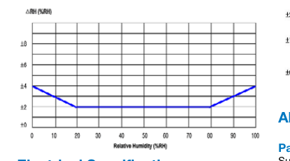
Individually calibrated and tested, ChipCap 2 performs at ±2% from 20% to 80% RH (±3% over entire humidity range), and is simple and ready to use without further calibration or temperature compensation.
ChipCap 2 provides linear output signals in various interfaces to customer requirements:
- I²C interface
- PDM convertible to analog signal
- Alarm function for preset control at min/ max humidity
Page 2
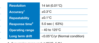
Sensor Performance
Temperature (°C)
Relative Humidity (RH%)
| Resolution | 14 bit (0.01%RH) |
| Accuracy1 | ±2.0 %RH (20~80%RH)2 |
| Repeatability | ±0.2 %RH |
| Hysteresis | ±2.0 %RH |
| Linearity | <2.0 %RH |
| Response time3 | 7.0 sec (τ 63%) |
| Temp Coefficient | Max 0.13 %RH/°C (at 10~60°C, 10~90%RH) |
| Operating Range | 0 ~ 100 %RH (Non-Condensing) |
| Long Term Drift | <0.5 %RH/yr (Normal condition) |
- Accuracies measured at 25°C, 5.0V 2. Min 5.0 sec, Max 20 sec
- Custom Accuracy Tolerance Available
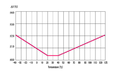
Typical Temperature Accuracy
- Accuracies measured at 25°C, 5.0V. 3. Measured at 25°C, 1m/sec airflow for achieving 63% of step
from 33%RH to 90%RH
Typical %RH Accuracy
Absolute Maximum Rating
Parameter
Min Max
Supply Voltage (VDD)
-0.3V 6.0V
Electrical Specifications
Storage Temp (Tstrg)
-55°C 150°C
Junction Temp (Tj)
-55°C 150°C
Supply Voltage
min 2.3V to max 5.5V
Soldering Information
Supply Current (IDD)
Standard or IR Solder Reflow
750 µA (typical)
Tp: 240°C, tp: 40 sec. (qualify Pb free profile)
Sleep Current (Isleep)
0.6 µA (typical)
Note: After soldering reconditioning will be required. Details for this process can be found in the
ChipCap® 2 application note (916-127).
Environmental
Package Contents
Operating Temperature Range
- 40 to 125°C
Capacitive polymer RH Sensor, PTA (Proportional to Absolute) Temperature sensor integrated ASIC chip in LCC (Leadless Chip Carrier)
Operating RH Range
package, SMD, RoHS compliant
0 to 100 % RH (non-condensing)
Page 3
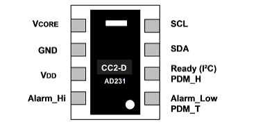
Pin Connection
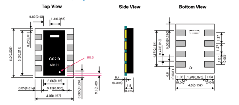
Dimensions (units: mm (inch))
Ordering Information
Telaire part no. Description
ChipCap® 2, analog, 2%, 5v
CC2A25
CC2A23
ChipCap 2, analog, 2%, 3.3v
CC2D23S
ChipCap 2, digital, sleep mode, 2%, 3.3v
CC2D25S
ChipCap 2, digital , sleep mode, 2%, 5v
CC2D23
ChipCap 2, digital, 2%, 3.3v
CC2D25
ChipCap 2, digital, 2%, 5v
CC2D35
ChipCap 2, digital, 3%, 5v
CC2A33
ChipCap 2, analog, 3%, 3.3v
CC2D33S
ChipCap 2, digital, sleep mode, 3%, 3.3v
CC2D35S
ChipCap 2, digital , sleep mode, 3%, 5v
CC2D33
ChipCap 2, digital, 3%, 3.3v
CC2A35
ChipCap 2, analog, 3%, 5v
Packaging Tape and Reel
Page 4
Important Safety Information
Telaire makes no warranty, representation or guarantee regarding the suitability of this product for any particular application, including safety critical applications. Nor does Telaire assume any liability arising out of the application or use in any product or circuit. Telaire specifically disclaims all liability without limitation consequential or incidental damages. No statuary or fitness for particular purpose shall be implied.
Warning
Before installing the product, review the product data sheet and application notes.
The product shall be used only within power supply and electrical input and output limits as specified by the datasheet and application notes.
Improper use of the product may result in product damage and property loss and/or personal injury.
Amphenol
Advanced Sensors
www.telaire.com
www.amphenol-sensors.com
© 2016 Amphenol Corporation. All Rights Reserved. Specifications are subject to change without notice. Other company names and product names used in this document are the registered trademarks or trademarks of their respective owners.
AAS-920-558D-02/2016