


 Download PDF
DATASHEET SEARCH SITE
Document overview
- PDF pages: 6
Technical content
Page 1
ESCC Qualified SMPS Capacitors
High Voltage Chip/Leaded Capacitors
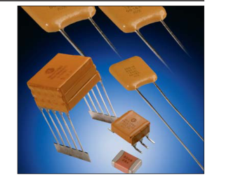
HIGH VOLTAGE CHIP CAPACITORS
Capacitors, Fixed, Chip, Ceramic Dielectric, Type II, High
Voltage, Based on Styles 1812 and 1825 for use in ESCC
space programs, according to ESCC Generic Specification
3009 and associated Detail Specification 3009/034 as
recommended by the Space Components Coordination
Group. (ranges in table below)
Note: Variants 01 to 12: metallized pads
| Size | Variant | Rated Voltage (kV) | Tolerance (%) | Capacitance Code (E12) |
| 1812 | 01 | 1.0 | ±10 | 392 - 223 |
| 02 | ±20 | |||
| 03 | 2.0 | ±10 | 152 - 182 | |
| 04 | ±20 | |||
| 05 | 3.0 | ±10 | 821 - 102 | |
| 06 | ±20 | |||
| 1825 | 07 | 1.0 | ±10 | 273 - 563 |
| 08 | ±20 | |||
| 09 | 2.0 | ±10 | 222 - 682 | |
| 10 | ±20 | |||
| 11 | 3.0 | ±10 | 821 - 392 | |
| 12 | ±20 |
HOW TO ORDER
Parts should be ordered using the ESCC variant number as follows:
3009034
Detail Spec Number
Eg 300903401C223
HIGH VOLTAGE LEADED CAPACITORS
Capacitors, Fixed, Ceramic Dielectric, Type II, High Voltage,
1.0 to 5.0 kV, Based on Case Styles VR, CV and CH for use
in ESCC space programs, according to ESCC Generic
Specification 3001 and associated Detail Specification
3001/034 as recommended by the Space Components
Coordination Group. (ranges in table)
Note 1: Lead Types a - Leaded Radial (epoxy coated) b - Leaded Radial (Polyurethane Varnish) c - Straight Dual in Line d - L Dual in Line Note 2: Tolerances of ±10% and ±20% are available
HOW TO ORDER
Parts should be ordered using the ESCC variant
number as follows:
3001034
XX
B
Type Variant
Test Level
Detail Spec
(per table above)
C = Standard test level
Number
B = Level C plus serialized and capacitance recorded before and after 100% burn-in.
Eg 300103412C274KM
XX
B
XXX
Type
Test Level
Capacitance
Variant
Code
C = Standard test level (per table)
The first two digits represent
B = Level C plus serialized
significant figures and the third
and capacitance
digit specifies the number of
recorded before and
zeros to follow; i.e.
after 100% burn-in.
102 = 1000pF 103 = 10000pF
| Case Size | Variant | Lead Type | Capacitance Code (E12) | ||||
|---|---|---|---|---|---|---|---|
| 1.0kV | 2.0kV | 3.0kV | 4.0kV | 5.0kV | |||
| VR30S | 01 | a | 392 - 203 | 152 - 182 | 821 - 102 | ||
| VR30 | 02 | a | 273 - 563 | 222 - 682 | 821 - 392 | ||
| VR40 | 03 | a | 473 - 124 | 822 - 153 | 472 - 103 | 182 - 222 | |
| VR50 | 04 | a | 154 - 274 | 183 - 333 | 123 - 183 | 562 - 822 | 332 - 392 |
| VR66 | 05 | a | 224 - 564 | 393 - 823 | 223 - 393 | 103 - 153 | 682 - 103 |
| VR84 | 06 | a | 684 - 105 | 473 - 154 | 473 - 683 | 183 - 393 | 123 - 183 |
| VR90 | 07 | a | 125 - 275 | 184 - 334 | 823 - 184 | 473 - 124 | 223 - 563 |
| CV41 | 08 | b | 473 - 124 | 822 - 153 | 472 - 103 | 182 - 222 | |
| CH41 | 09 | c | 473 - 124 | 822 - 153 | 472 - 103 | 182 - 222 | |
| CH41 | 10 | d | 473 - 124 | 822 - 153 | 472 - 103 | 182 - 222 | |
| CV51 | 11 | b | 154 - 274 | 183 - 333 | 123 - 183 | 562 - 822 | 332 - 392 |
| CH51 | 12 | c | 154 - 274 | 183 - 333 | 123 - 183 | 562 - 822 | 332 - 392 |
| CH51 | 13 | d | 154 - 274 | 183 - 333 | 123 - 183 | 562 - 822 | 332 - 392 |
| CV61 | 14 | b | 224 - 564 | 393 - 823 | 223 - 393 | 103 - 153 | 682 - 103 |
| CH61 | 15 | c | 224 - 564 | 393 - 823 | 223 - 393 | 103 - 153 | 682 - 103 |
| CH61 | 16 | d | 224 - 564 | 393 - 823 | 223 - 393 | 103 - 153 | 682 - 103 |
| CV76 | 17 | b | 684 - 105 | 473 - 154 | 473 - 683 | 183 - 393 | 123 - 183 |
| CH76 | 18 | c | 684 - 105 | 473 - 154 | 473 - 683 | 183 - 393 | 123 - 183 |
| CH76 | 19 | d | 684 - 105 | 473 - 154 | 473 - 683 | 183 - 393 | 123 - 183 |
| CV91 | 20 | b | 125 - 275 | 184 - 334 | 823 - 184 | 473 - 124 | 223 - 563 |
| CH91 | 21 | c | 125 - 275 | 184 - 334 | 823 - 184 | 473 - 124 | 223 - 563 |
| CH91 | 22 | d | 125 - 275 | 184 - 334 | 823 - 184 | 473 - 124 | 223 - 563 |
XXX
K
X
Capacitance
Capacitance
Voltage
Code
Tolerance
M = 1kV
The first two digits represent
K = 10%
P = 2kV
significant figures and the third
M = 20%
R = 3kV
digit specifies the number of
S = 4kV
zeros to follow; i.e.
Z = 5kV
102 = 1000pF 103 = 10000pF
Page 2
ESCC Qualified SMPS Capacitors
High Capacitance
HIGH CAPACITANCE LEADED CAPACITORS
Capacitors, Fixed, Ceramic Dielectric, Type II, High
Capacitance, Based on Case Styles BR, CV and CH for use
in ESCC space programs, according to ESCC Generic
Specification 3001 and associated Detail Specification
3001/030 as recommended by the Space Components
Coordination Group. (see ranges in table below)
| Case Size | Variant | Figure | Capacitance Code (E12) | |||
| 50V | 100V | 200V | 500V | |||
| BR40 | 01 | a | 185 - 335 | 125 - 275 | 334 - 564 | 124 - 224 |
| BR50 | 02 | a | 395 - 565 | 225 - 395 | 684 - 105 | 274 - 394 |
| BR66 | 03 | a | 685 - 106 | 475 - 825 | 105 - 225 | 474 - 105 |
| BR72 | 04 | a | 126 - 186 | 825 - 156 | 225 - 335 | 824 - 155 |
| BR84 | 05 | a | 126 - 186 | 825 - 156 | 225 - 335 | 824 - 155 |
| CV41 | 06 | b | 185 - 335 | 125 - 275 | 334 - 564 | 124 - 224 |
| CH41 | 07 | c | 185 - 335 | 125 - 275 | 334 - 564 | 124 - 224 |
| CH41 | 08 | d | 185 - 335 | 125 - 275 | 334 - 564 | 124 - 224 |
| CH42 | 09 | c | 395 - 685 | 335 - 565 | 684 - 125 | 274 - 474 |
| CH42 | 10 | d | 395 - 685 | 335 - 565 | 684 - 125 | 274 - 474 |
| CH43 | 11 | c | 825 - 106 | 685 - 825 | 155 - 185 | 564 - 684 |
| CH43 | 12 | d | 825 - 106 | 685 - 825 | 155 - 185 | 564 - 684 |
| CH44 | 13 | c | 126 | 106 | 225 | 824 - 105 |
| CH44 | 14 | d | 126 | 106 | 225 | 824 - 105 |
| CV51 | 15 | b | 395 - 565 | 225 - 395 | 684 - 105 | 274 - 394 |
| CH51 | 16 | c | 395 - 565 | 225 - 395 | 684 - 105 | 274 - 394 |
| CH51 | 17 | d | 395 - 565 | 225 - 395 | 684 - 105 | 274 - 394 |
| CH52 | 18 | c | 685 - 106 | 475 - 825 | 125 - 225 | 474 - 824 |
| CH52 | 19 | d | 685 - 106 | 475 - 825 | 125 - 225 | 474 - 824 |
| CH53 | 20 | c | 126 - 156 | 106 - 126 | 275 - 335 | 105 - 125 |
| CH53 | 21 | d | 126 - 156 | 106 - 126 | 275 - 335 | 105 - 125 |
| CH54 | 22 | c | 186 - 226 | 156 | 395 | 155 |
| CH54 | 23 | d | 186 - 226 | 156 | 395 | 155 |
| CV61 | 24 | b | 685 - 106 | 475 - 825 | 105 - 225 | 474 - 105 |
| CH61 | 25 | c | 685 - 106 | 475 - 825 | 105 - 225 | 474 - 105 |
| CH61 | 26 | d | 685 - 106 | 475 - 825 | 105 - 225 | 474 - 105 |
| CH62 | 27 | c | 126 - 226 | 106 - 156 | 275 - 475 | 105 - 185 |
| CH62 | 28 | d | 126 - 226 | 106 - 156 | 275 - 475 | 105 - 185 |
| CH63 | 29 | c | 276 - 336 | 186 - 226 | 565 - 685 | 225 - 275 |
| CH63 | 30 | d | 276 - 336 | 186 - 226 | 565 - 685 | 225 - 275 |
| CH64 | ˜31 | c | 396 | 276 - 336 | 825 - 106 | 335 |
| CH64 | 32 | d | 396 | 276 - 336 | 825 - 106 | 335 |
| CV71 | 33 | b | 126 - 186 | 825 - 156 | 225 - 335 | 824 - 155 |
| CH71 | 34 | c | 126 - 186 | 825 - 156 | 225 - 335 | 824 - 155 |
| CH71 | 35 | d | 126 - 186 | 825 - 156 | 225 - 335 | 824 - 155 |
| CH72 | 36 | c | 226 - 396 | 186 - 276 | 395 - 685 | 185 - 335 |
| CH72 | 37 | d | 226 - 396 | 186 - 276 | 395 - 685 | 185 - 335 |
HOW TO ORDER
Note 1: Lead Types a - Leaded Radial (epoxy coated) b - Leaded Radial (Polyurethane Varnish) c - Straight Dual in Line d - L Dual in Line Note 2: Tolerances of ±10% and ±20% are available
| Case Size | Variant | Figure | Capacitance Code (E12) | |||
| 50V | 100V | 200V | 500V | |||
| CH73 | 38 | c | 476 - 566 | 336 - 396 | 825 - 106 | 395 - 475 |
| CH73 | 39 | d | 476 - 566 | 336 - 396 | 825 - 106 | 395 - 475 |
| CH74 | 40 | c | 686 | 476 | 126 | 565 |
| CH74 | 41 | d | 686 | 476 | 126 | 565 |
| CV76 | 42 | b | 126 - 186 | 825 - 156 | 225 - 335 | 824 - 155 |
| CH76 | 43 | c | 126 - 186 | 825 - 156 | 225 - 335 | 824 - 155 |
| CH76 | 44 | d | 126 - 186 | 825 - 156 | 225 - 335 | 824 - 155 |
| CH77 | 45 | c | 226 - 396 | 186 - 276 | 395 - 685 | 185 - 335 |
| CH77 | 46 | d | 226 - 396 | 186 - 276 | 395 - 685 | 185 - 335 |
| CH78 | 47 | c | 476 - 566 | 336 - 396 | 825 - 106 | 395 - 475 |
| CH78 | 48 | d | 476 - 566 | 336 - 396 | 825 - 106 | 395 - 475 |
| CH79 | 49 | c | 686 | 476 | 126 | 565 |
| CH79 | 50 | d | 686 | 476 | 126 | 565 |
| CH81 | 51 | c | 156 - 226 | 126 - 186 | 225 - 395 | 824 - 155 |
| CH81 | 52 | d | 156 - 226 | 126 - 186 | 225 - 395 | 824 - 155 |
| CH82 | 53 | c | 276 - 476 | 226 - 396 | 475 - 825 | |
| CH82 | 54 | d | 276 - 476 | 226 - 396 | 475 - 825 | |
| CH83 | 55 | c | 566 - 686 | 476 - 566 | 106 - 126 | |
| CH83 | 56 | d | 566 - 686 | 476 - 566 | 106 - 126 | |
| CH84 | 57 | c | 826 | 686 | 156 | |
| CH84 | 58 | d | 826 | 686 | 156 | |
| CH86 | 59 | c | 226 - 336 | 156 - 276 | 395 - 685 | 155 - 225 |
| CH86 | 60 | d | 226 - 336 | 156 - 276 | 395 - 685 | 155 - 225 |
| CH87 | 61 | c | 396 - 686 | 336 - 566 | 825 - 156 | |
| CH87 | 62 | d | 396 - 686 | 336 - 566 | 825 - 156 | |
| CH88 | 63 | c | 826 - 107 | 686 - 826 | 186 - 226 | |
| CH88 | 64 | d | 826 - 107 | 686 - 826 | 186 - 226 | |
| CH89 | 65 | c | 127 | 107 | 276 | |
| CH89 | 66 | d | 127 | 107 | 276 | |
| CH91 | 67 | c | 396 - 476 | 336 - 396 | 825 - 106 | |
| CH91 | 68 | d | 396 - 476 | 336 - 396 | 825 - 106 | |
| CH92 | 69 | c | 566 - 107 | 476 - 826 | 126 - 226 | |
| CH92 | 70 | d | 566 - 107 | 476 - 826 | 126 - 226 | |
| CH93 | 71 | c | 127 - 157 | 107 - 127 | 276 - 336 | |
| CH93 | 72 | d | 127 - 157 | 107 - 127 | 276 - 336 | |
| CH94 | 73 | c | 187 | 157 | 396 | |
| CH94 | 74 | d | 187 | 157 | 396 | |
Parts should be ordered using the ESCC variant number as follows:
3001030
XX
B
Type Variant
Test Level
Detail Spec
(per table above)
C = Standard test level
Number
B = Level C plus serialized and capacitance recorded before and after 100% burn-in.
EG 300103018C106KC
Lot Acceptance Testing is available for all our ESCC qualified ranges. LAT 1 42 samples → 12 mechanical + 20 life test + 6 for TC + 4 for solder LAT 2 30 samples → 20 life test + 6 for TC + 4 for solder LAT 3 10 samples → 6 for TC + 4 for solder
XXX
K
X
Capacitance
Capacitance
Voltage
Code
Tolerance
C = 50V
The first two digits represent
K = 10%
E = 100V
significant figures and the third
M = 20%
G = 200V
digit specifies the number of
L = 500V
zeros to follow; i.e. 102 = 1000pF 103 = 10000pF
Page 3
ESCC DETAIL SPECIFICATION NO. 3009/034
PHYSICAL DIMENSIONS
Millimeters (Inches)
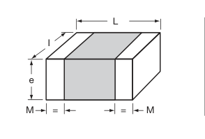
| Symbol | Variants 01 to 06 | Variants 07 to 12 | ||
|---|---|---|---|---|
| Min. | Max. | Min. | Max. | |
| L | 4.20 (0.165) | 5.00 (0.197) | 4.20 (0.165) | 5.00 (0.197) |
| l | 2.80 (0.110) | 3.60 (0.142) | 5.67 (0.223) | 6.67 (0.263) |
| e | – | 3.00 (0.118) | – | 3.30 (0.130) |
| M | 0.25 (0.010) | 0.75 (0.030) | 0.25 (0.010) | 0.75 (0.030) |
ESCC DETAIL SPECIFICATION NO. 3001/034
PHYSICAL DIMENSIONS – VR STYLE
Millimeters (Inches)
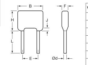
| Variant | Case Size | B | Ød | E | F | H | J | L | ||
| Max. | Min. | Max. | Min. | Max. | Max. | Max. | Max. | Min. | ||
| 01 | VR30S | 7.62 (0.300) | 0.46 (0.018) | 0.56 (0.022) | 4.58 (0.180) | 5.58 (0.220) | 5.00 (0.197) | 4.60 (0.181) | 1.50 (0.059) | 31.7 (1.248) |
| 02 | VR30 | 7.62 (0.300) | 0.46 (0.018) | 0.56 (0.022) | 4.58 (0.180) | 5.58 (0.220) | 5.00 (0.197) | 9.62 (0.379) | 1.50 (0.059) | 31.7 (1.248) |
| 03 | VR40 | 10.16 (0.400) | 0.46 (0.018) | 0.56 (0.022) | 4.58 (0.180) | 5.58 (0.220) | 5.00 (0.197) | 11.7 (0.461) | 1.50 (0.059) | 31.7 (1.248) |
| 04 | VR50 | 12.7 (0.500) | 0.59 (0.023) | 0.69 (0.027) | 9.66 (0.380) | 10.66 (0.420) | 5.10 (0.201) | 14.2 (0.559) | 1.50 (0.059) | 31.7 (1.248) |
| 05 | VR66 | 17.5 (0.689) | 0.86 (0.034) | 0.96 (0.038) | 14.2 (0.559) | 15.2 (0.598) | 6.40 (0.252) | 16.5 (0.650) | 1.50 (0.059) | 31.7 (1.248) |
| 06 | VR84 | 23.62 (0.930) | 0.86 (0.034) | 0.96 (0.038) | 20.4 (0.803) | 22.0 (0.866) | 6.40 (0.252) | 19.78 (0.779) | 1.50 (0.059) | 31.7 (1.248) |
| 07 | VR90 | 23.5 (0.925) | 0.86 (0.034) | 0.96 (0.038) | 20.4 (0.803) | 22.0 (0.866) | 6.40 (0.252) | 42.0 (1.654) | 1.50 (0.059) | 31.7 (1.248) |
ESCC DETAIL SPECIFICATION NO. 3001/034
PHYSICAL DIMENSIONS – CV STYLE
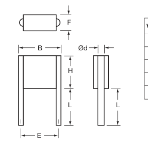
Millimeters (Inches)
| Variant | Case Size | B | Ød | E | F | H | L | |||
| Max. | Min. | Max. | Min. | Max. | Max. | Max. | Min. | Max. | ||
| 08 | CV41 | 10.6 (0.417) | 0.65 (0.026) | 0.75 (0.030) | 7.70 (0.303) | 8.70 (0.343) | 3.80 (0.150) | 8.70 (0.343) | 22.0 (0.866) | 28.0 (1.102) |
| 11 | CV51 | 11.9 (0.469) | 0.85 (0.033) | 0.95 (0.037) | 9.66 (0.380) | 10.66 (0.420) | 3.80 (0.150) | 10.7 (0.421) | 22.0 (0.866) | 28.0 (1.102) |
| 14 | CV61 | 16.5 (0.650) | 0.85 (0.033) | 0.95 (0.037) | 14.74 (0.580) | 15.74 (0.620) | 3.80 (0.150) | 13.6 (0.535) | 22.0 (0.866) | 28.0 (1.102) |
| 17 | CV76 | 22.7 (0.894) | 0.85 (0.033) | 0.95 (0.037) | 20.4 (0.803) | 22.0 (0.866) | 3.80 (0.150) | 16.6 (0.654) | 22.0 (0.866) | 28.0 (1.102) |
| 20 | CV91 | 22.7 (0.894) | 1.15 (0.045) | 1.25 (0.049) | 20.4 (0.803) | 22.0 (0.866) | 3.80 (0.150) | 40.6 (1.598) | 22.0 (0.866) | 28.0 (1.102) |
Page 4
ESCC DETAIL SPECIFICATION NO. 3001/034
PHYSICAL DIMENSIONS – CH STYLE, D.I.L.
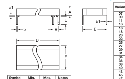
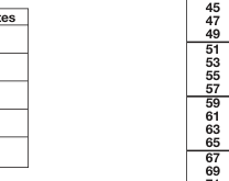
| Symbol | Min. | Max. | Notes |
|---|---|---|---|
| a1 | - | 2.00 (0.079) | 1 |
| b | 0.45 (0.018) | 0.55 (0.022) | 1 |
| b1 | 0.204 (0.008) | 0.304 (0.012) | 1 |
| e | 2.49 (0.098) | 2.59 (0.102) | 2 |
| L | 12.0 (0.472) | 14.0 (0.551) | 1 |
Notes: 1 – All leads 2 – Each space
ESCC DETAIL SPECIFICATION NO. 3001/034
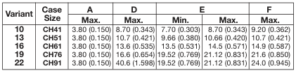
PHYSICAL DIMENSIONS – CH STYLE, L
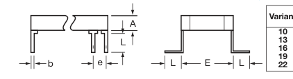
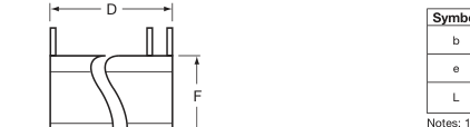
Millimeters (Inches)
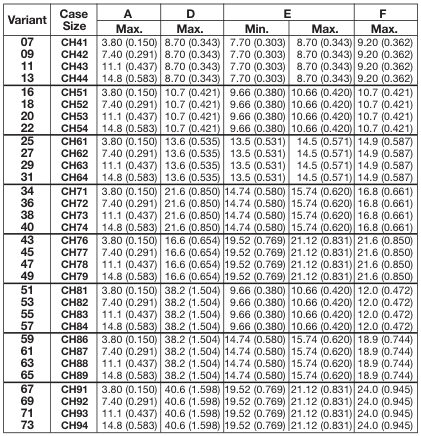
Millimeters (Inches)
| Symbol | Min. | Max. | Notes |
|---|---|---|---|
| b | 0.45 (0.018) | 0.55 (0.022) | 1 |
| e | 2.49 (0.098) | 2.59 (0.102) | 2 |
| L | 2.04 (0.080) | 3.01 (0.120) | 1 |

Page 5
ESCC DETAIL SPECIFICATION NO. 3001/030 PHYSICAL DIMENSIONS – BR STYLE
Millimeters (Inches)
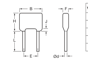
| Variant | Case Size | B | Ød | E | F | H | J | L | ||
| Max. | Min. | Max. | Min. | Max. | Max. | Max. | Max. | Min. | ||
| 01 | BR40 | 10.16 (0.400) | 0.46 (0.018) | 0.56 (0.022) | 4.58 (0.180) | 5.58 (0.220) | 5.00 (0.197) | 11.7 (0.461) | 1.50 (0.059) | 31.7 (1.248) |
| 02 | BR50 | 12.7 (0.500) | 0.59 (0.023) | 0.69 (0.027) | 9.66 (0.380) | 10.66 (0.420) | 5.10 (0.201) | 14.2 (0.559) | 1.50 (0.059) | 31.7 (1.248) |
| 03 | BR66 | 17.5 (0.689) | 0.86 (0.034) | 0.96 (0.038) | 14.2 (0.559) | 15.2 (0.598) | 6.40 (0.252) | 16.5 (0.650) | 1.50 (0.059) | 31.7 (1.248) |
| 04 | BR72 | 19.3 (0.760) | 0.86 (0.034) | 0.96 (0.038) | 14.74 (0.580) | 15.74 (0.620) | 6.40 (0.252) | 24.0 (0.945) | 1.50 (0.059) | 31.7 (1.248) |
| 05 | BR84 | 23.62 (0.930) | 0.71 (0.028) | 0.81 (0.032) | 18.93 (0.745) | 20.83 (0.820) | 6.40 (0.252) | 19.78 (0.779) | 1.50 (0.059) | 31.7 (1.248) |
ESCC DETAIL SPECIFICATION NO. 3001/030 PHYSICAL DIMENSIONS – CV STYLE
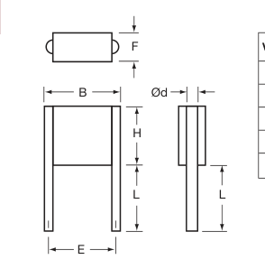
Millimeters (Inches)
| Variant | Case Size | B | Ød | E | F | H | L | |||
| Max. | Min. | Max. | Min. | Max. | Max. | Max. | Min. | Max. | ||
| 06 | CV41 | 10.6 (0.417) | 0.65 (0.026) | 0.75 (0.030) | 7.70 (0.303) | 8.70 (0.343) | 3.80 (0.150) | 8.70 (0.343) | 22.0 (0.866) | 28.0 (1.102) |
| 15 | CV51 | 11.9 (0.469) | 0.85 (0.033) | 0.95 (0.037) | 9.66 (0.380) | 10.66 (0.420) | 3.80 (0.150) | 10.7 (0.421) | 22.0 (0.866) | 28.0 (1.102) |
| 24 | CV61 | 16.5 (0.650) | 0.85 (0.033) | 0.95 (0.037) | 14.74 (0.580) | 15.74 (0.620) | 3.80 (0.150) | 13.6 (0.535) | 22.0 (0.866) | 28.0 (1.102) |
| 33 | CV71 | 17.8 (0.701) | 0.85 (0.033) | 0.95 (0.037) | 14.74 (0.580) | 15.74 (0.620) | 3.80 (0.150) | 21.6 (0.850) | 22.0 (0.866) | 28.0 (1.102) |
| 42 | CV76 | 22.7 (0.894) | 0.85 (0.033) | 0.95 (0.037) | 20.4 (0.803) | 22.0 (0.866) | 3.80 (0.150) | 16.6 (0.654) | 22.0 (0.866) | 28.0 (1.102) |
Page 6
ESCC DETAIL SPECIFICATION NO. 3001/030
PHYSICAL DIMENSIONS – CH STYLE, D.I.L.
Millimeters (Inches)
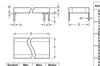
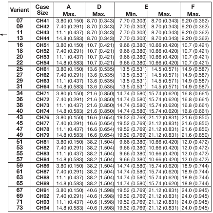
| Symbol | Min. | Max. | Notes |
|---|---|---|---|
| a1 | - | 2.00 (0.079) | 1 |
| b | 0.45 (0.018) | 0.55 (0.022) | 1 |
| b1 | 0.204 (0.008) | 0.304 (0.012) | 1 |
| e | 2.49 (0.098) | 2.59 (0.102) | 2 |
| L | 2.04 (0.080) | 3.04 (0.120) | 1 |
Notes: 1 – All leads 2 – Each space
ESCC DETAIL SPECIFICATION NO. 3001/030
PHYSICAL DIMENSIONS – CH STYLE, L
Millimeters (Inches)
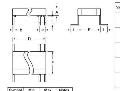
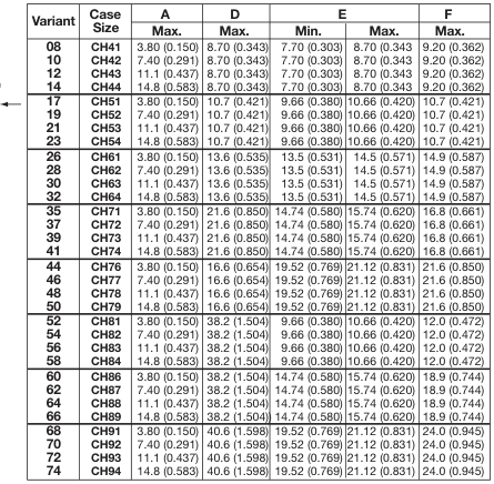
| Symbol | Min. | Max. | Notes |
|---|---|---|---|
| b | 0.45 (0.018) | 0.55 (0.022) | 1 |
| e | 2.49 (0.098) | 2.59 (0.102) | 2 |
| L | 2.04 (0.080) | 3.04 (0.120) | 1 |
Notes: 1 – All leads 2 – Each space