Download PDF
CBT6810_02 PHILIPS
Document overview
- PDF pages: 9
Technical content
Page 1
INTEGRATED CIRCUITS
Supersedes data of 2000 Jun 19
Philips Semiconductors
Page 2
FEATURES
- 5 Ω switch connection between port A and port B
- TTL compatible input and output levels
- Undershoot protection included to prevent shoot through level changes
- Bias voltage pre-charges the outputs to minimize signal distortion during live insertion
- Latch-up protection exceeds 500 mA per JESD78
- ESD protection exceeds 2000 V HBM per JESD22-A114, 200 V MM per JESD22-A115 and 1000 V CDM per JESD22-C101
QUICK REFERENCE DATA
DESCRIPTION
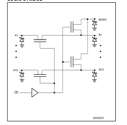
The CBT6810 provides ten bits of high-speed TTL-compatible bus switching. The low on-state resistance of the switch allows bi-directional connections to be made while adding near-zero propagation delay. The device also precharges the B port to a user-selectable bias voltage (BIASV) to minimize live-insertion noise. The CBT6810 is organized as one 10-bit switch with a single enable (OE) input. When OE is low, the switch is on and port A is connected to port B. When OE is high, the switch between port A and port B is open and the B port is precharged to BIASV through the equivalent of a 10-kΩ resistor. The CBT6810 is characterized for operation from -40 to +85 °C.
| SYMBOL | PARAMETER | CONDITIONS Tamb = 25 °C; GND = 0 V | TYPICAL | UNIT |
|---|---|---|---|---|
| tPLH tPHL | Propagation delay An to Bn or Bn to An | CL = 50 pF; VCC = 5 V | 250 | ps |
| CIN | Input capacitance | VI = 0 V or VCC | 3.5 | pF |
| CIO | Input/output capacitance | Outputs disabled; VO = 0 V or VCC | 9.0 | pF |
ORDERING INFORMATION
| PACKAGES | TEMPERATURE RANGE | ORDER CODE | DWG NUMBER |
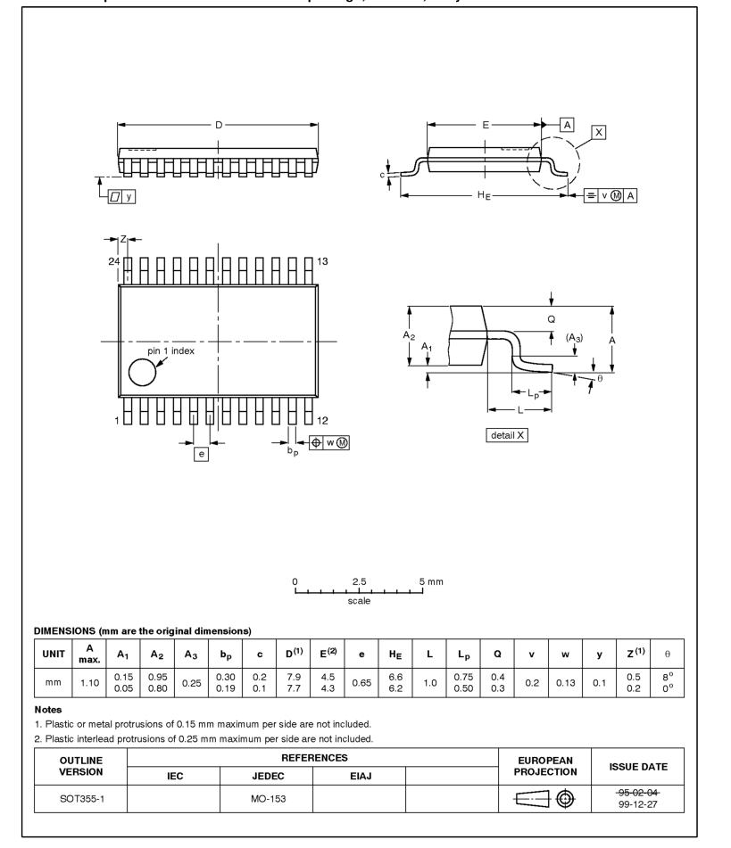
| 24-Pin Plastic TSSOP | -40 to +85 °C | CBT6810PW | SOT355-1 |
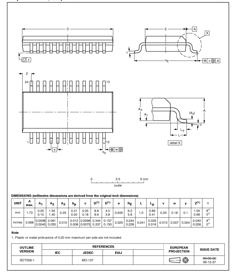
| 24-Pin Plastic SSOP (QSOP) | -40 to +85 °C | CBT6810DK | SOT556-1 |
PIN CONFIGURATION
PIN DESCRIPTION
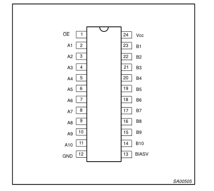
| PIN NUMBER | SYMBOL | NAME AND FUNCTION |
|---|---|---|
| 1 | OE | Output enable |
| 13 | BIASV | Precharge bias voltage input |
| 2, 3, 4, 5, 6, 7, 8, 9, 10, 11 | A1-A10 | A - port side |
| 23, 22, 21, 20, 19, 18, 17, 16, 15, 14 | B1-B10 | B - port side with active pullup |
| 12 | GND | Ground (V) |
| 24 | VCC | Positive supply voltagem |
Page 3
LOGIC SYMBOL
FUNCTION TABLE
| OE | STATE |
| L | A port = B port |
| H | A port = Z |
| H | B port = BIASV |
H = High voltage level L = Low voltage level Z = High impedance “off” state
ABSOLUTE MAXIMUM RATINGS1, 2
| SYMBOL | PARAMETER | CONDITIONS | RATING | UNIT |
|---|---|---|---|---|
| VCC | DC supply voltage | -0.5 to +7.0 | V | |
| IIK | DC clamp diode current | -50 | mA | |
| VI | DC input voltage3 | -0.5 to +7.0 | V | |
| ISW | DC continuous channel current | ± 128 | mA | |
| Tstg | Storage temperature range | -65 to 150 | °C | |
| BIASV | DC Bias voltage range | -0.5 to 7.0 | V | |
| ΘJA | Power dissipation per package Plastic thin shrink small outline package | 134 | °C/W |
NOTES:
- Stresses beyond those listed may cause permanent damage to the device. These are stress ratings only and functional operation of the device at these or any other conditions beyond those indicated under “recommended operating conditions” is not implied. Exposure to absolute-maximum-rated conditions for extended periods may affect device reliability. 2. The performance capability of a high-performance integrated circuit in conjunction with its thermal environment can create junction temperatures which are detrimental to reliability. The maximum junction temperature of this integrated circuit should not exceed 150°C. 3. The input and output voltage ratings may be exceeded if the input and output current ratings are observed.
Page 4
RECOMMENDED OPERATING CONDITIONS
| SYMBOL | PARAMETER | LIMITS | UNIT | |
|---|---|---|---|---|
| Min | Max | |||
| VCC | DC supply voltage | 4.0 | 5.5 | V |
| BIASV | DC supply voltage | 1.3 | VCC | V |
| VIH | High-level input voltage (control pin) | 2.0 | — | V |
| VIL | Low-level Input voltage (control pin) | — | 0.8 | V |
| Tamb | Operating free-air temperature range | -40 | +85 | °C |
DC ELECTRICAL CHARACTERISTICS
| SYMBOL | PARAMETER | TEST CONDITIONS | LIMITS | UNIT | ||
|---|---|---|---|---|---|---|
| Tamb = -40 to +85 °C | ||||||
| Min | Typ1 | Max | ||||
| VIK | Input clamp voltage | VCC = 4.5 V; II = -18 mA | — | — | -1.2 | V |
| II | Input leakage current (control pin) | VCC = 5.5 V; VI = GND or 5.5 V | — | — | ± 5 | µA |
| IO | Output bias current (B pins) | VCC = 4.5 V; BiasV = 2.4 V; VO = 0, OE = VCC | — | — | -0.25 | mA |
| ICC | Quiescent supply current | VCC = 5.5 V; IO = 0, VI = VCC or GND | — | — | 2.5 | mA |
| ∆ICC | Control pins2 | VCC = 5.5 V, one input at 3.4 V, other inputs at VCC or GND | — | — | 2.5 | mA |
| CI | Control pins | VI= 3 V or 0 | — | 3.5 | — | pF |
| CO(OFF) | Terminal capacitance | VO = 3 V or 0; switch off | — | 9.0 | — | pF |
| roonn3 | On-resistance | VCC = 4.5 V; VI = 0 V; II = 64 mA | — | 5 | 7 | Ω |
| VCC = 4.5 V; VI = 0 V; II = 30 mA | — | 5 | 7 | |||
| VCC = 4.5 V; VI = 2.4 V; II = -15 mA | — | 10 | 15 | |||
| VP | Pass voltage | VIN = VCC = 5.0 V; Iout = -100 µA | 3.4 | 3.6 | 3.9 | V |
| IUSP4 | Undershoot static current protection | VCC = 5.0 V, BiasV = VCC IB = -5 µA, VB ≥3 V | — | -10 | — | mA |
NOTES:
- All typical values are at VCC = 5 V, Tamb = 25°C 2. This is the increase in supply current for each input that is at the specified TTL voltage level rather than VCC or GND 3. Measured by the voltage drop between the A and the B terminals at the indicated current through the switch. On-state resistance is determined by the lowest voltage of the two (A or B) terminals. 4. Force IUSP, measure VB ≥ 3 V
Page 5
AC CHARACTERISTICS FOR VCC = 5.0 ±0.5 V RANGE
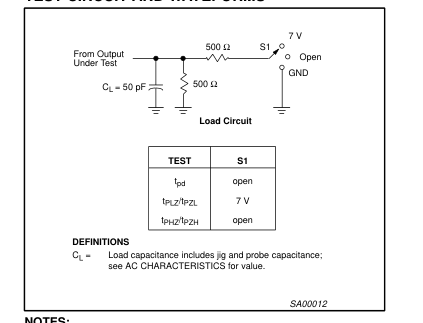
GND = 0 V; tr = tf ≤ 2.5 ns; CL = 50 pF.
| SYMBOL | PARAMETER | WAVEFORM | LIMITS | UNIT | ||
|---|---|---|---|---|---|---|
| Tamb = -40 to +85°C | ||||||
| MIN | TYP1 | MAX | ||||
| tpd | Propagation delay An to Bn; Bn to An2 | 1 | 0.25 | ns | ||
| tPZH | 3-State output enable time OE to An; OE to Bn; BIASV = GND | 2 | 1.8 | 3.5 | 5.3 | ns |
| tPZL | 3-State output enable time OE to An; OE to Bn; BIASV = 3.0V | 2 | 2.1 | 4.2 | 7.2 | ns |
| tPHZ | 3-State output enable time OE to An; OE to Bn; BIASV = GND | 2 | 1.7 | 3.7 | 6.1 | ns |
| tPLZ | 3-State output enable time OE to An; OE to Bn; BIASV = 3.0V | 2 | 1.0 | 5.5 | 7.3 | ns |
NOTE:
- All typical values are measured at Tamb = 25 °C and VCC = 5.0 V 2. Warranted but not production tested. The propagation delay is based on the RC time constant of the typical ON-state resistance of the switch and a load capacitance of 50pF, when driven by an ideal voltage source (zero output impedance)
AC WAVEFORMS
VM = 1.5V, VIN = GND to 3.0V
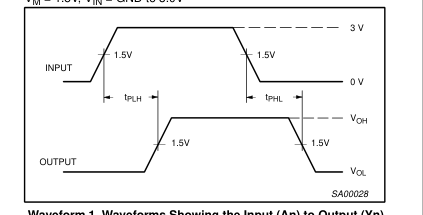
Waveform 1. Waveforms Showing the Input (An) to Output (Yn)
Propagation Delays
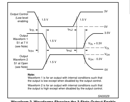
Waveform 2. Waveforms Showing the 3-State Output Enable
and Disable Times
TEST CIRCUIT AND WAVEFORMS
NOTES:
- All input pulses are supplied by generators having the following characteristics: PRR ≤ 10 MHz, ZO = 50 Ω, tr ≤ 2.5 ns, tf ≤ 2.5 ns. 2. The outputs are measured one at a time with one transition per measurement.
Page 6
TSSOP24: plastic thin shrink small outline package; 24 leads; body width 4.4 mm
SOT355-1
Page 7
SSOP24: plastic shrink small outline package; 24 leads; body width 3.9 mm; lead pitch 0.635 mm
SOT556-1
Page 8
REVISION HISTORY
| Rev | Date | Description |
|---|---|---|
| _3 | 20021213 | Product data (9397 750 10871); ECN 853-2151 29159 of 06 November 2002. Modifications: • New package release. |
| _2 | 20000619 | Product data (9397 750 07214); ECN 853-2151 23905 of 19 June 2000. |
Page 9
Data sheet status
| Level | Data sheet status[1] | Product status[2] [3] | Definitions |
| I | Objective data | Development | This data sheet contains data from the objective specification for product development. Philips Semiconductors reserves the right to change the specification in any manner without notice. |
| II | Preliminary data | Qualification | This data sheet contains data from the preliminary specification. Supplementary data will be published at a later date. Philips Semiconductors reserves the right to change the specification without notice, in order to improve the design and supply the best possible product. |
| III | Product data | Production | This data sheet contains data from the product specification. Philips Semiconductors reserves the right to make changes at any time in order to improve the design, manufacturing and supply. Relevant changes will be communicated via a Customer Product/Process Change Notification (CPCN). |
[1] Please consult the most recently issued data sheet before initiating or completing a design. [2] The product status of the device(s) described in this data sheet may have changed since this data sheet was published. The latest information is available on the Internet at URL http://www.semiconductors.philips.com. [3] For data sheets describing multiple type numbers, the highest-level product status determines the data sheet status.
Definitions
Short-form specification — The data in a short-form specification is extracted from a full data sheet with the same type number and title. For detailed information see the relevant data sheet or data handbook. Limiting values definition — Limiting values given are in accordance with the Absolute Maximum Rating System (IEC 60134). Stress above one or more of the limiting values may cause permanent damage to the device. These are stress ratings only and operation of the device at these or at any other conditions above those given in the Characteristics sections of the specification is not implied. Exposure to limiting values for extended periods may affect device reliability.
Application information — Applications that are described herein for any of these products are for illustrative purposes only. Philips Semiconductors make no representation or warranty that such applications will be suitable for the specified use without further testing or modification.
Disclaimers
Life support — These products are not designed for use in life support appliances, devices, or systems where malfunction of these products can reasonably be expected to result in personal injury. Philips Semiconductors customers using or selling these products for use in such applications do so at their own risk and agree to fully indemnify Philips Semiconductors for any damages resulting from such application. Right to make changes — Philips Semiconductors reserves the right to make changes in the products—including circuits, standard cells, and/or software—described or contained herein in order to improve design and/or performance. When the product is in full production (status ‘Production’), relevant changes will be communicated
via a Customer Product/Process Change Notification (CPCN). Philips Semiconductors assumes no responsibility or liability for the use of any of these products, conveys no license or title under any patent, copyright, or mask work right to these products, and makes no representations or warranties that these products are free from patent, copyright, or mask work right infringement, unless otherwise specified.
Contact information
For additional information please visit http://www.semiconductors.philips.com. Fax: +31 40 27 24825
For sales offices addresses send e-mail to: sales.addresses@www.semiconductors.philips.com.
Koninklijke Philips Electronics N.V. 2002 All rights reserved. Printed in U.S.A.
Date of release: 12-02
Document order number:
9397 750 10871