


 Download PDF
C8855 HAMAMATSU
Document overview
- PDF pages: 2
Technical content
Page 1

USB INTERFACE COMPATIBLE
COUNTING UNIT
C8855
OVER VIEW
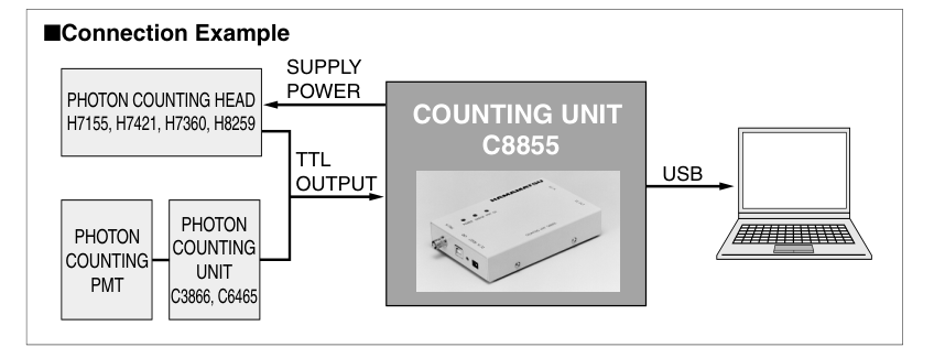
The C8855 is a counting unit with a USB interface and can be used as a photon counter when combined with a photon counting head, etc. The counter of the C8855 has two counter circuits (double counter method) capable of counting input signals with no dead time. The USB interface easily connects to a notebook PC allowing measurement in an even wider application field. When used with a photon counting head, the C8855 supplies power (+5 V / 200 mA) necessary to operate the photon counting head. Since the C8855 is hot-swap compatible (plug and play compatible), it helps you set up measurement environment quickly. You can start measurement on the day the C8855 is
delivered by using the sample software that supplied with the C8855.
FEATURES
GCompatible with USB interface (Ver. 1.1) GCompatible with Windows® 98/98SE/2000/Me GSample software supplied as standard item GAccurate measurement with no dead time
(double counter method)
GSupplies power to operate photon counting head
(power supply capacity: +5 V / 200 mA)
The C8855 cannot be used in simultaneous dual- channel measurements or long-time measurements with a fast time resolution. In such applications, use the M8784 counting board also available from Hamamatsu.
- Time-resolved measurement (minimum resolution: 50 µs) for monitoring weak light detection like chemiluminescence or biological clocks
- Quick measurement setups (hot-swap compatible) You can start measurement by just connecting the USB cable without restarting the PC, if required software (device driver, etc) is installed into your PC beforehand.
- Applicable to various measurement methods The C8855 is fully controlled by DLL (dynamic link library) functions that supplied with the C8855. User can create own software program, which is adequate for various type of user measurement, based on the DLL functions.
Page 2
SPECIFICATIONS
| Parameter | Description / Value | |
|---|---|---|
| Input | Number of Input Signals | 1 ch |
| Signal Input Level | TTL positive logic | |
| Signal Pulse Width | 8 ns or longer | |
| Input Impedance | 50 Ω | |
| Counter | Counter Method | Double counter method |
| Max.Count Rate | 50 MHz | |
| Max.Counter Capacity | 232 counts/counter gate | |
| Counter Gate | Counter Gate Mode | Internal counter gate only |
| Internal Counter Gate Time | 50 µs to 10 s (1, 2, 5 step) | |
| Trigger | Trigger Method | Software or external trigger |
| External Trigger Signal | TTL negative logic | |
| General Output Section | Open collector / 2 bits | |
| Voltage Output | +5 V / 200 mA Max. | |
| Compatible OS | Windows® 98/98SE/Me/2000 | |
| Interface | USB (Ver. 1.1) | |
| Supply Voltage | +5 V / 500 mA Max. (supplied from accessory AC adapter) | |
| Dimensions | (W): 148 mm × (D): 96 mm × (H): 30 mm (excluding rubber feet and projecting par | |
| Weight | 300 g | |
| Operating Ambient Temperature / Humidity | +5 °C to +45 °C / 80 % or less (no condensation) | |
| Storage Temperature / Humidity | 0 °C to +50 °C / 85 % or less (no condensation) | |
| AC Adapter | Input | AC 90 V to AC 260 V |
| Output | 7 V / 1.6 A | |
Supplied: CD-ROM (containing instruction manual, device driver, DLL, sample software\*, etc.) USB cable, AC adapter, AC cable, power output connector \*: Sample software is configured from Lab VIEW™ of National Instruments, Inc. : Conforms to the EMC directive (89/336/EEC) and the low voltage directive (73/23/EEC) of the European Union.
BLOCK DIAGRAM
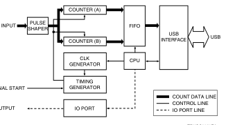
SIGNAL INPUT
EXTERNAL START
2 BIT OUTPUT
TPHOC0050EA
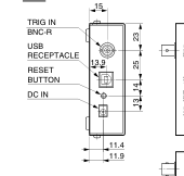
DIMENSIONAL OUTLINES (Unit: mm)
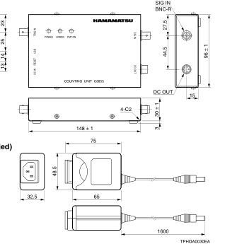
AC adapter (Supplied)
Windows® is a registered trademark of Microsoft Corporation in the United States and/or other countries. Lab VIEW™ is a trademark of National Instruments, Inc. Other product and software names mentioned herein may be either registered trademarks or trademarks of their respective owners. Subject to local technical requirements and regulations, availability of products included in this promotional material may vary. Please consult with our sales office. Information furnished by HAMAMATSU is believed to be reliable. However, no responsibility is assumed for possible inaccuracies or omissions. Specifications are subject to change without notice. No patent rights are granted to any of the circuits described herein. ©2002 Hamamatsu Photonics K.K.
WEB SITE http://www.hamamatsu.com
HAMAMATSU PHOTONICS K.K., Electron Tube Center 314-5, Shimokanzo, Toyooka-village, Iwata-gun, Shizuoka-ken, 438-0193, Japan, Telephone: (81)539/62-5248, Fax: (81)539/62-2205 U.S.A.: Hamamatsu Corporation: 360 Foothill Road, P. O. Box 6910, Bridgewater. N.J. 08807-0910, U.S.A., Telephone: (1)908-231-0960, Fax: (1)908-231-1218 E-mail: usa@hamamatsu.com Germany: Hamamatsu Photonics Deutschland GmbH: Arzbergerstr. 10, D-82211 Herrsching am Ammersee, Germany, Telephone: (49)8152-375-0, Fax: (49)8152-2658 E-mail: info@hamamatsu.de France: Hamamatsu Photonics France S.A.R.L.: 8, Rue du Saule Trapu, Parc du Moulin de Massy, 91882 Massy Cedex, France, Telephone: (33)1 69 53 71 00, Fax: (33)1 69 53 71 10 E-mail: infos@hamamatsu.fr
United Kingdom: Hamamatsu Photonics UK Limited: 2 Howard Court, 10 Tewin Road Welwyn Garden City Hertfordshire AL7 1BW, United Kingdom, Telephone: 44-(0)1707-294888, Fax: 44(0)1707-325777 E-mail: info@hamamatsu.co.uk North Europe: Hamamatsu Photonics Norden AB: Smidesvägen 12, SE-171-41 SOLNA, Sweden, Telephone: (46)8-509-031-00, Fax: (46)8-509-031-01 E-mail: info@hamamatsu.se
TPHO1021E01
Italy: Hamamatsu Photonics Italia: S.R.L.: Strada della Moia, 1/E, 20020 Arese, (Milano), Italy, Telephone: (39)02-935 81 733, Fax: (39)02-935 81 741 E-mail: info@hamamatsu.it
JAN. 2003 IP