

 Download PDF
C7921CA HAMAMATSU
Document overview
- PDF pages: 7
Technical content
Page 1
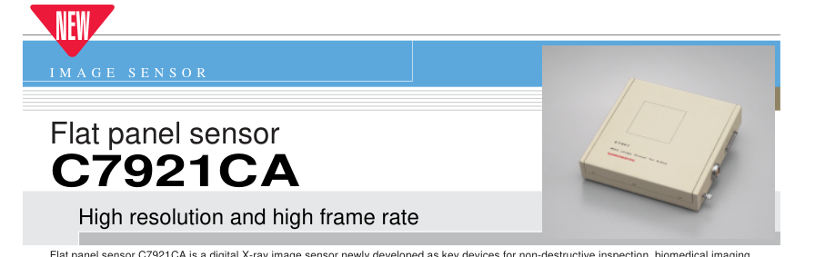
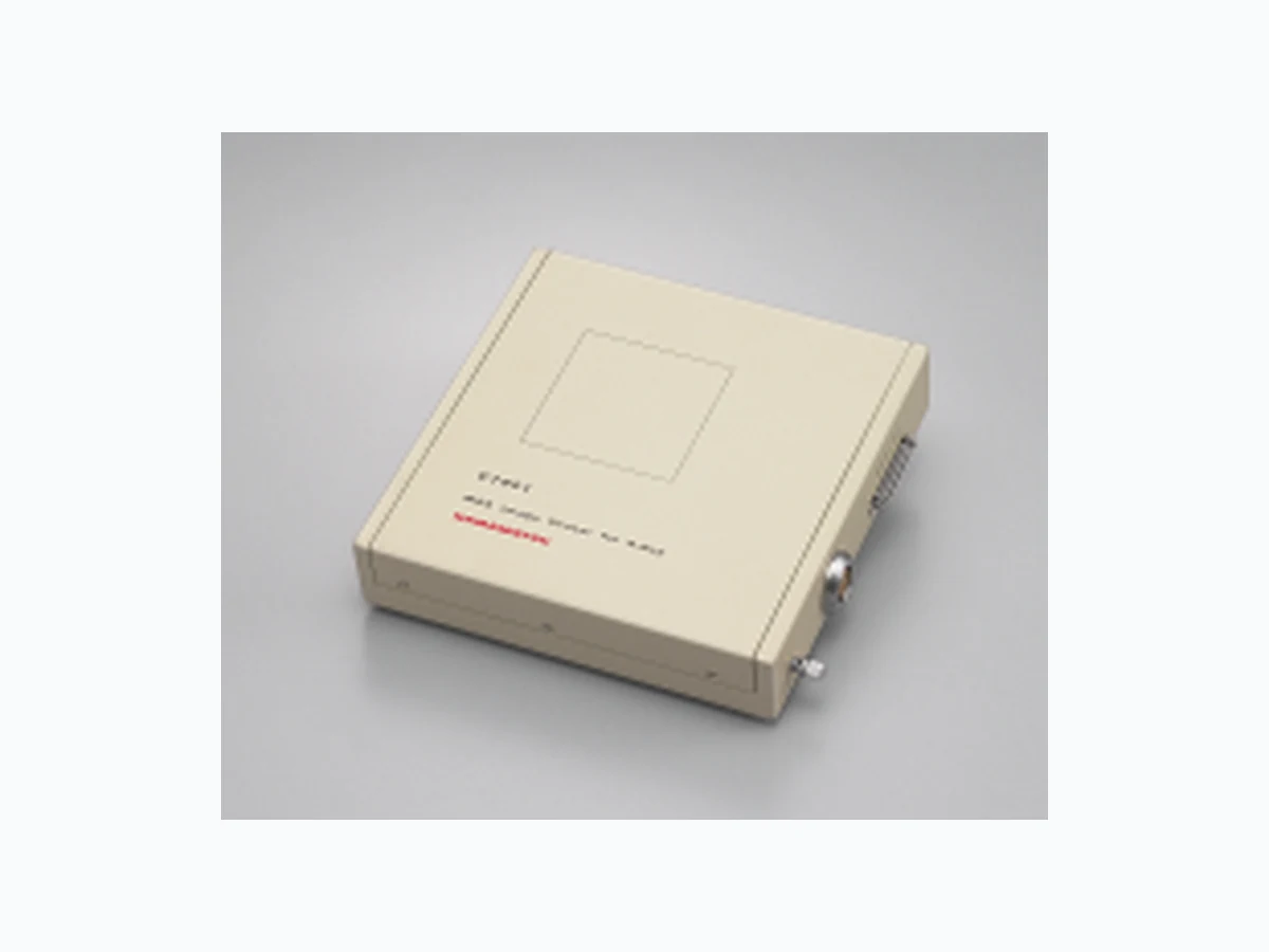
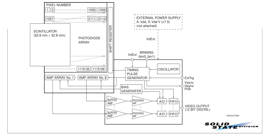
Flat panel sensor C7921CA is a digital X-ray image sensor newly developed as key devices for non-destructive inspection, biomedical imaging, X-ray microscopy and other real-time X-ray imaging applications requiring high resolution and high image quality. C7921CA consists of a sensor board and a control board, both assembled in a thin, flat and compact package. The sensor board contains a CsI scintillator plate, a twodimensional photodiode array with FET switches and a signal processing IC chip. The photodiode array has a 1056 × 1056 pixel format with minimized blooming and is highly sensitive to bluish green light emitted from the CsI scintillator. Each row of pixels is addressed in sequence by
the vertical shift register connected to the gate line. Light emission occurs when X-rays are absorbed in the CsI scintillator. This light emission enters directly into the two-dimensional photodiode array where an electric charge is stored in each pixel according to the light intensity. This charge is then transferred to the corresponding data line by applying a control signal to the vertical shift register. The sensor board also has 8 charge sensitive amplifier arrays each having 132 channel amplifiers with a horizontal shift register. These amplifiers with a total of 1056 channels are connected to a CDS (Correlated Double Sampling) circuit that senses the charge on each video line and sends it
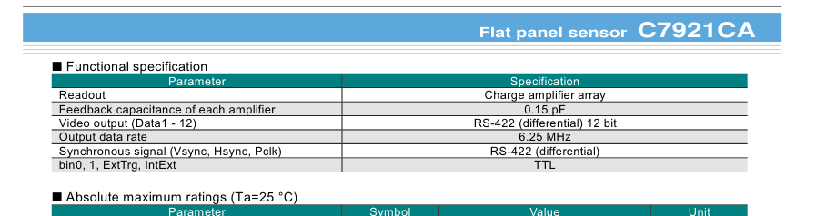
as the analog video signal from each amplifier array. The control board converts the analog video signal into a 12-bit digital signal and outputs it to an external frame grabber from a 12-bit parallel port. C7921CA delivers a frame rate of 16 frames per second using 4 × 4 binning and is ideal for high frame rate applications, also ideal for applications requiring high resolution because of its 50 µm pixel size. Massive digital image data can easily be monitored on a display unit by using a frame grabber board and video memory installed in the PC. C7921CA will prove ideal tools for real-time X-ray imaging and processing where easy-to-use, high-resolution X-ray digital image sensors are needed.

l Digital output (12 bits) l High-speed imaging by binning operation: 16 frames/s (4 × 4 binning) l Wide dynamic range
I Block diagram
l High cost performance
Page 2
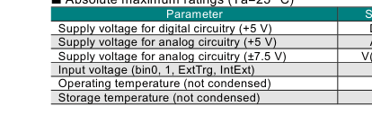
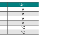
| Symbol | Value |
|---|---|
| D.vdd | +6.0 |
| A.vdd | +6.0 |
| V(+/-7.5) | ±12 |
| Vin | 0 to 6.0 |
| Topr | 0 to +35 |
| Tstg | 0 to +50 |
I Specification (Unless otherwise noted, Typ. Ta=25 °C A.vdd= 5.0 V, D.vdd= 5.0 V, V (±7.5)= ±7.5 V)
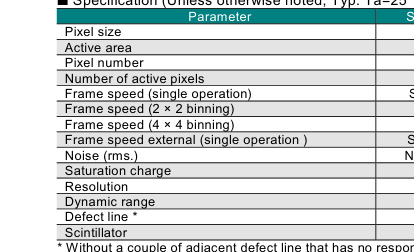
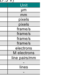
| Symbol | Specification |
|---|---|
| - | 50 |
| - | 52.8 × 52.8 |
| - | 1056 × 1056 |
| - | 1032 × 1032 |
| Sf (int) | 4 |
| - | 8 |
| - | 16 |
| Sf (ext) | Sf (int) to 0.1 |
| N (rms.) | 1000 |
| Csat | 2.9 |
| Reso | 8 |
| - | 2900 |
| - | 10 Max. |
| - | CsI |
Page 3
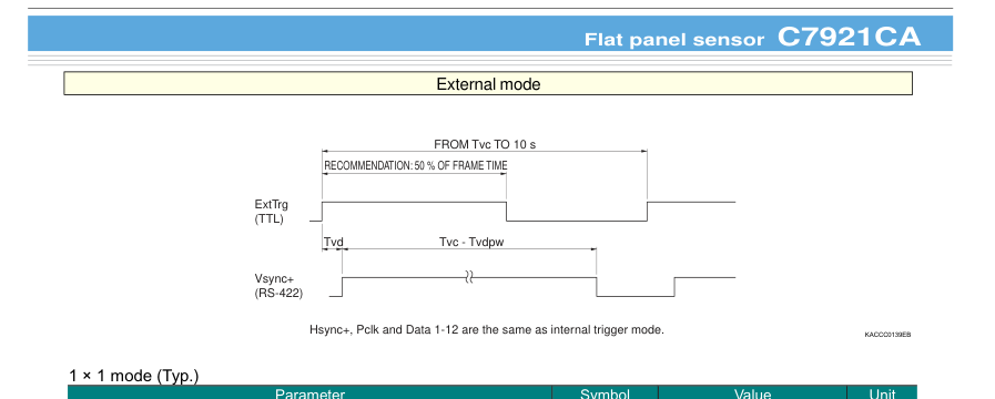
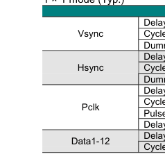
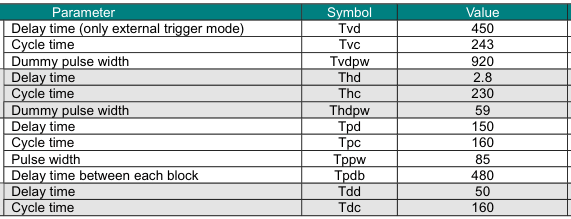
µs ms µs µs µs µs ns ns ns ns ns ns
2 × 2 mode (Typ.)
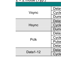
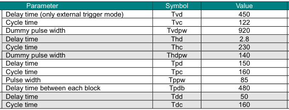
Unit µs ms µs µs µs µs ns ns ns ns ns ns
4 × 4 mode (Typ.)
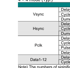
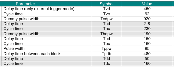
Unit µs ms µs µs µs µs ns ns ns ns ns ns
Note) The numbers of siginificant figures is two. (except Tvc)
Page 4
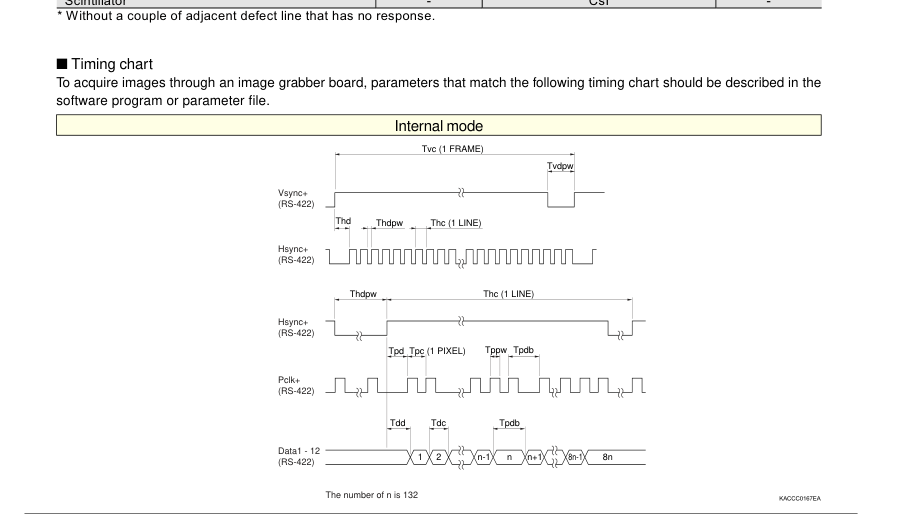
I System requirements To operate C7921CA at full performance, the following system and peripherals are required. PC: IBM compatible PC running on Windows 98 or later operating system Digital frame grabber card: Monochrome 16 bits or more, pixel clock 7 MHz or more, RS-422 interface synchronous signal (See the frame grabber manual.) The National Instruments IMAQ PCI-1424 (NI parts No. 777662-01) frame grabber has been verified to successfully acquire 12- bit digital images from C7921CA. The IMAQ PCI-1422 (NI pats No. 777959-01) also acquires satisfactory images from C7921CA. You can utilize the demonstration software that comes with the frame grabber as a simple viewer, to acquire and save an image.
To do so, refer to the frame grabber user’s guide for how to use the camera information file for the demonstration software.
Power source: A. Vdd = +5.0 ± 0.1 V (700 mA), D. Vdd = +5.0 ± 0.1 V (800 mA), V (±7.5) = ±7.5 ± 0.5 V (±100 mA). Use of a series power supply is recommended. (Avoid using a switching power supply.) A power cable (terminated with an FGG.2B.307.CLAD92Z plug at one end and open at the other end; 2 m; see Table 2.) comes supplied with C7921CA. An optional 36-pin cable for interface with the 36-pin receptacle (see Table 1) on C7921CA is also available for synchronous signal input, video output and external control. The voltages described above are specified at the flat panel sensor side. The impedance of the power cable attached with the flat panel sensor is low enough but it causes 0.1 V approx. drop. Therefore the voltage at the power source side should be set
0.1 V higher than the voltage specified above.
Table 1 Pin assignment of 36-pin receptacle
| Signal | Pin No. |
| Data1+ (MSB) | 19 |
| Data2+ | 20 |
| Data3+ | 21 |
| Data4+ | 22 |
| Data5+ | 23 |
| Data6+ | 24 |
| Data7+ | 25 |
| Data8+ | 26 |
| Data9+ | 27 |
| Data10+ | 28 |
| Data11+ | 29 |
| Data12+(LSB) | 30 |
| bin0 (TTL) | 31 |
| bin1 (TTL) | 32 |
| ExtTrg (TTL) | 33 |
| Vsync+ | 34 |
| Hsync+ | 35 |
| Pclk+ | 36 |
Pin No.
Signal
1
Data1- (MSB)
2
Data2-
3
Data3-
4
Data4-
5
Data5-
6
Data6-
7
Data7-
8
Data8-
9
Data9-
10
Data10-
11
Data11-
12
Data12- (LSB)
13
Gnd
14
Gnd
15
IntExt (TTL)
16
Vsync-
17
Hsync-
18
Pclk-
Unless otherwise noted, signal level is RS-422. 36-pin receptacle: TX20A-36R-D2GF1-A1L made by JAE (Japan Aviation Electronics Industry limited) 36-pin mating plug: TX20A-36PH1-D2P1-D1 made by JAE (Japan Aviation Electronics Industry limited)
Table 2 Power pin assignment and cable color Pin No.
Color
Signal
1
Brown
+7.5 V
2
Red
Analog GND
3
Orange
-7.5 V
4
Yellow
Analog GND
5
Green
Analog +5 V
6
Blue
Digital GND
7
Purple
Digital +5 V
Shield
-
Analog GND
7-pin power plug: FGG.2B.307.CLAD92Z made by LEMO S. A. (http://www.lemo.ch) 7-pin power receptacle: ECG.2B.307.CLV made by LEMO S. A.
Page 5
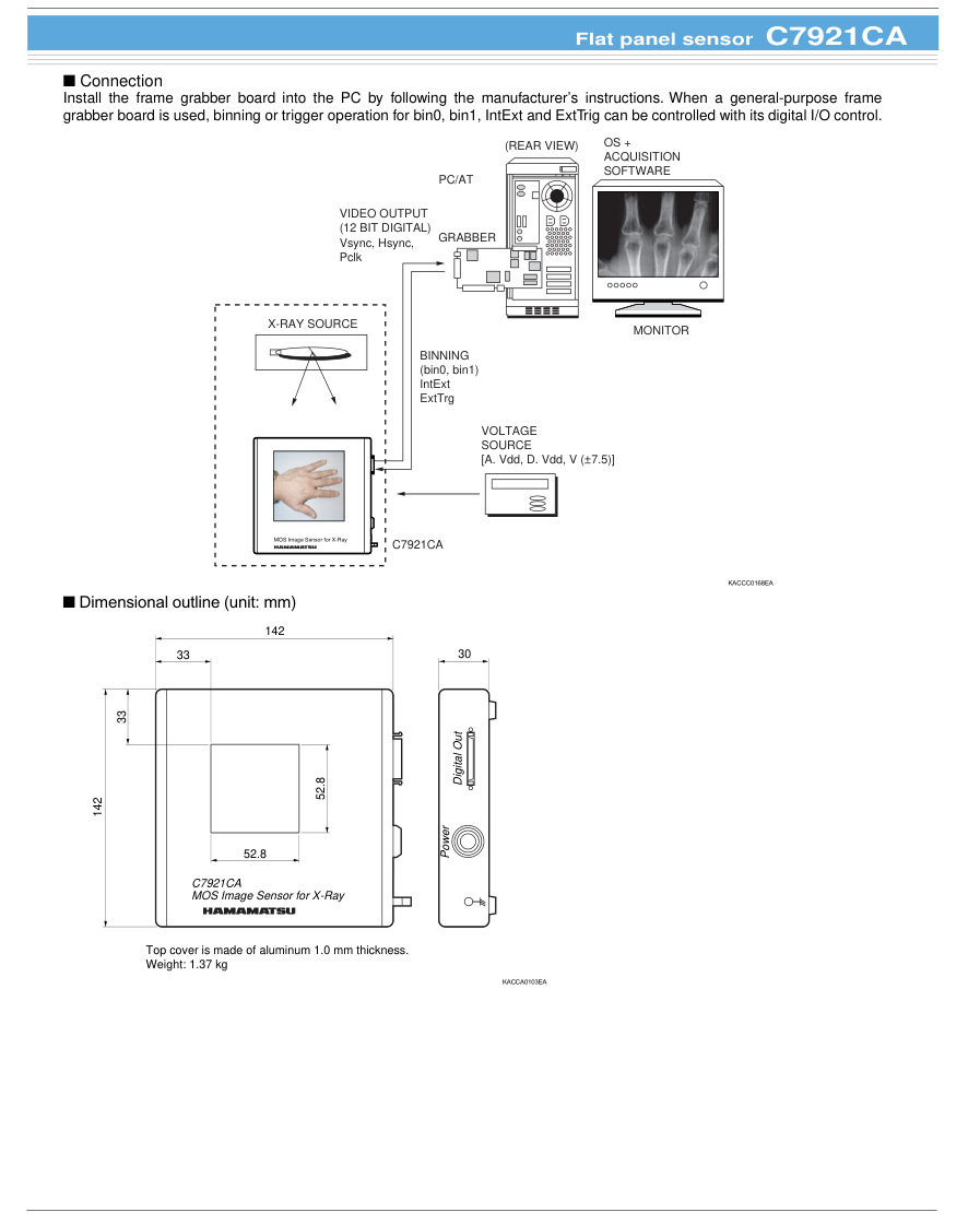
Page 6
General purpose frame grabber cable A8406-01/-06/-07/-08
Optional 36-pin cables
Two types of 36-pin cables are provided as options for connecting to the frame grabber. Type A (A8406-01): General-purpose interface cable for digital flame grabber. Type B (A8406-02): Interface cable for IMAQ PCI-1424 grabber board.
| Cable type No. | Cable length | Cable end |
|---|---|---|
| A8406-01 | 5 m | TX20A-36PH1-D2P1-D1 *1 |
| A8406-06 | 7 m | |
| A8406-07 | 10 m | |
| A8406-08 | 12 m | |
| A8406-02 | 5 m | |
| A8406-03 | 7 m | |
| A8406-04 | 10 m | |
| A8406-05 | 12 m |
Type
Cable end
A
open
PCS-XE100MA \*2
B
\*1: Made by JAE (Japan Aviation Electronics Industry, Limited) \*2: Made by Honda Tsushin Kogyo Co. Ltd.
A8406-01/-06/-07/-08 cable for general frame grabber
A8406-01/-06/-07/-08 is a cable that connects the flat panel sensor (C7921CA, etc.) to a general frame grabber. One end of this cable has a 36-pin plug mating with the C7921CA digital output receptacle, but the other end is left open. Connect the open end to a plug that mates with the frame grabber to be used. Cable color coding and specifications are shown in the table below.
I Cable color coding and specifications
| Signal | Cable color | Marking color | Pin No. | Signal | Cable color |
| Data1+ (MSB) | blue | - | 19 | Data1- (MSB) | orange |
| Data2+ | green | - | 20 | Data2- | brown |
| Data3+ | gray | - | 21 | Data3- | red |
| Data4+ | black | - | 22 | Data4- | yellow |
| Data5+ | pink | - | 23 | Data5- | purple |
| Data6+ | white | - | 24 | Data6- | blue |
| Data7+ | orange | white | 25 | Data7- | green |
| Data8+ | brown | white | 26 | Data8- | gray |
| Data9+ | red | white | 27 | Data9- | black |
| Data10+ | yellow | black | 28 | Data10- | pink |
| Data11+ | purple | white | 29 | Data11- | white |
| Data12+ (LSB) | blue | red | 30 | Data12- (LSB) | orange |
| bin0 (TTL) | green | white | 31 | Gnd | brown |
| bin1 (TTL) | gray | white | 32 | Gnd | red |
| ExtTrg (TTL) | black | white | 33 | IntExt (TTL) | yellow |
| Vsync+ | pink | black | 34 | Vsync- | purple |
| Hsync+ | white | blue | 35 | Hsync- | blue |
| Pclk+ | orange | black | 36 | Pclk- | green |
Pin No.
Marking color
1
-
2
-
3
-
4
-
5
-
6
red
7
white
8
white
9
white
10
black
11
blue
12
white
13
white
14
white
15
black
16
white
17
black
18
black
I Dimensional outline (unit: mm)
a
18 36
1 19
36-PIN CABLE
TX20A-36PH1-D2P1-D1
| Cable type No. | a |
|---|---|
| A8406-01 | 5000 ± 140 |
| A8406-06 | 7000 ± 140 |
| A8406-07 | 10000 ± 140 |
| A8406-08 | 12000 ± 140 |
KACCA0096EB
Page 7
Digital frame grabber cable for IMAQ PCI-1424 A8406-02/-03/-04/-05
A8406-02/-03/-04/-05 cable for IMAQ PCI-1424 frame grabber
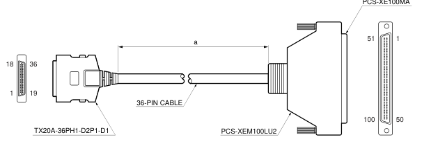
A8406-02/-03/-04/-05 cable is designed to connect the flat panel sensor (C7921CA, etc.) to the National Instrument IMAQ PCI- 1424 and PCI-1422 digital frame grabber board. Both ends of this cable have connectors. One end is a 36-pin plug mating with the C7921CA digital output receptacle, while the other end is a 100-pin plug for the IMAQ PCI-1424 and PCI-1422. I Pin connection for A8406-02
| TX20A-36PH1-D2P1-D1 Pin No. | Signal | PCS-XE100MA Pin No. | TX20A-36PH1-D2P1-D1 Pin No. | Signal | PCS-XE100MA Pin No. |
| 1 | Data1+ (MSB) | 23 | 19 | Data1- (MSB) | 24 |
| 2 | Data2+ | 21 | 20 | Data2- | 22 |
| 3 | Data3+ | 19 | 21 | Data3- | 20 |
| 4 | Data4+ | 17 | 22 | Data4- | 18 |
| 5 | Data5+ | 15 | 23 | Data5- | 16 |
| 6 | Data6+ | 13 | 24 | Data6- | 14 |
| 7 | Data7+ | 11 | 25 | Data7- | 12 |
| 8 | Data8+ | 9 | 26 | Data8- | 10 |
| 9 | Data9+ | 7 | 27 | Data9- | 8 |
| 10 | Data10+ | 5 | 28 | Data10- | 6 |
| 11 | Data11+ | 3 | 29 | Data11- | 4 |
| 12 | Data12+ (LSB) | 1 | 30 | Data12- (LSB) | 2 |
| 13 | bin0 (TTL) | 33 | 31 | Gnd | 99 |
| 14 | bin1 (TTL) | 35 | 32 | Gnd | 100 |
| 15 | ExtTrg (TTL) | 37 | 33 | IntExt (TTL) | 39 |
| 16 | Vsync+ | 41 | 34 | Vsync- | 42 |
| 17 | Hsync+ | 43 | 35 | Hsync- | 44 |
| 18 | Pclk+ | 49 | 36 | Pclk- | 50 |
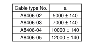
I Dimensional outline (unit: mm)
PCS-XE100MA
KACCA0097EB
Notice) · Do not subject the Flat Panel Sensors to strong vibration or shock. (Strong shock such as drop impacts may cause permanent damage to these sensors.)
- Users must take responsibility for implementing X-ray shielding safety measures to avoid the risk of X-ray exposure.
- This product was not designed and manufactured for use as a medical X-ray device. System manufacturers must take responsibility for obtaining MHW or FDA approval when incorporating this product into a medical diagnostics system.
- This product is warranted for a period of 12 months after the date of the shipment. The warranty is limited to make a replacement or repair of any defective material due to defects in workmanship or materials used in manufacture. It does not cover loss or damage of the product due to natural calamity, misuse or total radiation dose over 1 million Roentgen (80 kV) even within the warranty period.
Information furnished by HAMAMATSU is believed to be reliable. However, no responsibility is assumed for possible inaccuracies or omissions. Specifications are subject to change without notice. No patent rights are granted to any of the circuits described herein. ©2003 Hamamatsu Photonics K.K.
HAMAMATSU PHOTONICS K.K., Solid State Division 1126-1 Ichino-cho, Hamamatsu City, 435-8558 Japan, Telephone: (81) 053-434-3311, Fax: (81) 053-434-5184, http://www.hamamatsu.com U.S.A.: Hamamatsu Corporation: 360 Foothill Road, P.O.Box 6910, Bridgewater, N.J. 08807-0910, U.S.A., Telephone: (1) 908-231-0960, Fax: (1) 908-231-1218 Germany: Hamamatsu Photonics Deutschland GmbH: Arzbergerstr. 10, D-82211 Herrsching am Ammersee, Germany, Telephone: (49) 08152-3750, Fax: (49) 08152-2658 France: Hamamatsu Photonics France S.A.R.L.: 8, Rue du Saule Trapu, Parc du Moulin de Massy, 91882 Massy Cedex, France, Telephone: 33-(1) 69 53 71 00, Fax: 33-(1) 69 53 71 10
United Kingdom: Hamamatsu Photonics UK Limited: 2 Howard Court, 10 Tewin Road, Welwyn Garden City, Hertfordshire AL7 1BW, United Kingdom, Telephone: (44) 1707-294888, Fax: (44) 1707-325777 North Europe: Hamamatsu Photonics Norden AB: Smidesvägen 12, SE-171 41 Solna, Sweden, Telephone: (46) 8-509-031-00, Fax: (46) 8-509-031-01 Italy: Hamamatsu Photonics Italia S.R.L.: Strada della Moia, 1/E, 20020 Arese, (Milano), Italy, Telephone: (39) 02-935-81-733, Fax: (39) 02-935-81-741
Cat. No. KACC1066E05 Sep. 2003 DN