

 Download PDF
C7700 HAMAMATSU
Document overview
- PDF pages: 4
Technical content
Page 1
High Dynamic Range Streak Camera
C7700
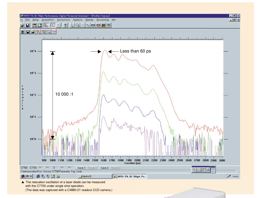
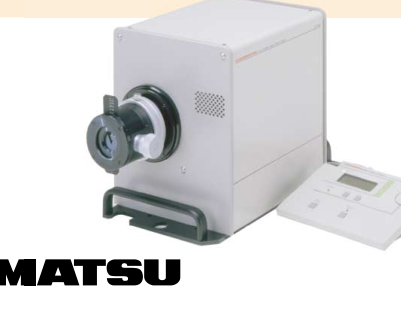
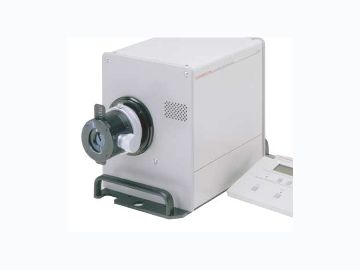
The C7700 is a newly developed high dynamic range streak camera that can handle a large number of photoelectrons. This feature enables single-shot measurements of ultrafast phenomena with a D-range as high as 10 000 : 1. This system is suitable for high-precision simultaneous measurement of high-intensity and weak intensity pulse light.
Page 2
High Dynamic Range Measure
(light → electrons)
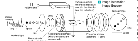
2 Streak Tube
[Operating Principle]
The light pulse to be measured is focused onto the photocathode of the streak tube through the slit, where the photons are converted into a number of electrons proportional to the intensity of the incident light. These electrons are accelerated and conducted towards the phosphor screen, and a high-speed voltage which is synchronized to the incident light is applied. The electrons are swept at high speed from top to bottom, after which they are bombarded against the phosphor screen of the streak tube and converted to an optical image. When the light intensity of the streak image is very weak, an image intensifier or an image booster amplifies the low light level streak
image.
D-range of 10 000:1 of ultrafast phenomena under single-shot operation
FEATURES
G High dynamic range of 10 000:1\*
G Temporal resolution of 5 ps\*
G Effective photocathode size: 17 mm
G Simultaneous measurement of light intensity
on temporal and spatial (wavelength) axis
G IEEE 488 (GP-IB) control
\*[About a Dynamic Range]
The maximum dynamic range of the streak camera essence is set to 1000:1 by the measurement condition of temporal resolution 5ps, and is set to 10 000:1 by the measurement condition of temporal-resolution 100ps. With a light intensity, the image intensifier tube, such as an image intensifier or an image booster, is combined with a streak camera. In this case, the image intensifier tube may restrict the dynamic range of the measurement system. Furthermore, a read-out camera may also restrict the dynamic range of the measurement system.
| Readout Camera | Image Intensifier Tube | Temporal Resolution | |
| 5 ps | 100 ps | ||
| C4880-21 | Image Intensifier | 1000:1 | 2000:1 |
| Image Booster | - | 10 000:1 | |
| ORCA2 | Image Intensifier | 1000:1 | 2000:1 |
| Image Booster | - | 3000:1 | |
APPLICATIONS
G Research involving laser fusion lasers, free
electron lasers and various other types of
pulsed lasers
G Plasma light emission, radiation, laser ab-
lation, combustion and explosion
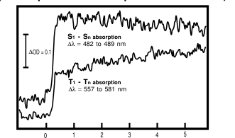
G Picosecond transient absorption measurement
(Time dependence of absorption is shown below.)
Time (ns)
L The 266 nm excitation (25 ps, 0.2 mJ, 2 mm focused, single shot) of Chrysene in THF (0.5 mmol/l)
G LIDAR, Thomson scattering, time-of-flight
laser ranging
G Fluorescence lifetime measurement, time-
resolved Raman spectroscopy
Page 3
ment Possible up to 10 000:1
SPECIFICATIONS
1 Input Optics
| Type No. | Spectral Transmission | Effective F Value | Image Multiplica- tion Ratio | Slit Width | Slit Width Reading Precision | Overall Length |
|---|---|---|---|---|---|---|
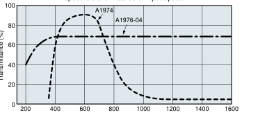
| A1974 | 400 nm to 900 nm | 1.2 | 1 : 1 | 0 to 5 mm | 5 µm | 159 mm |
| A1976-04 | 200 nm to 1060 nm | 3.5 | 1 : 1 | 98.2 mm |
Spectral transmittance of input optics
Wavelength (nm)
2 Streak Tube
| Type No. | Streak Tube | Spectral Response Characteristic | Effective Photocathode Size | Phosphor Screen | Spatial Resolution |
|---|---|---|---|---|---|
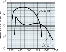
| C7700-01 | N8059 | 200 nm to 850 nm | 7 mm × 17 mm | • Phosphor screen characteristic P-43 • Fiber-optic output • Effective Phos- phor screen size: 25 mm | 18 lp/mm or more centered on photocathode Note) read- out camera ORCA2 |
| C7700-11 | N8059-02 | 300 nm to 1060 nm |
Spectral response characteristics
Wavelength (nm)
3 Main Unit
G Streak Unit
- Temporal resolution:
better than 5 ps (at the fastest sweep
range)
- Sweep time/full screen 0.5, 1, 2, 5, 10, 20, 50, 100, 200, 500 ns
1, 2, 5, 10, 20, 50, 100, 200, 500 µs, 1 ms
- Trigger jitter:
less than ±20 ps (at the fastest
sweep range)
- Trigger delay:
about 25 ns (at the fastest sweep range)
- Maximum sweep repetition frequency
..........................................1 kHz (at the fastest sweep range)
- Operating mode ................................................. Focus/Streak
- Trigger input
Maximum input voltage ........................................... ±5 V/50 Ω
Trigger level .................................................... ±4 V Adjustable
- Gating mode ............................. NORMAL, Gate, Open Fixed
- Gating method ...................................... Photocathode Gating
- Gate trigger input ......................................... 3.5 Vto 5.0 V/50 Ω
- Gate repetition frequency ............................................ 100 Hz
- Gate delay time .............................................................. 1 µs
4 Image Intensifier (I.I.), Image Booster (I.B.)
| Type No. | Photocathode | Effective Photocathode Size | Phosphor Screen | Luminous Gain |
|---|---|---|---|---|
| V3346U-04 (I.I.) | S-20 | 25 mm | P-43 | 3000 |
| V3346U-24 (I.B.) | 15 (typ.) |
5 Output Optics
| Type No. | Magnification | Effective F-number | Readeout Camera |
|---|---|---|---|
| A7702-02 | 1 : 0.7 | F = 2.0 | C4880-21 |
| A2098 | 2 : 1 | F = 2.5 | ORCA2 |
6 Readout Cameras
| Type No. | Imaging Device | Effective No. of Pixels | Pixel Size |
|---|---|---|---|
| C4880-21 | Full frame transfer CCD | 512(H)× 512 (V) | 24 µm × 24 µm |
| ORCA2 | Progressive-scan interline CCD | 12 80(H)× 1024(V) | 6.7 µm × 6.7 µm |
7 Readout System
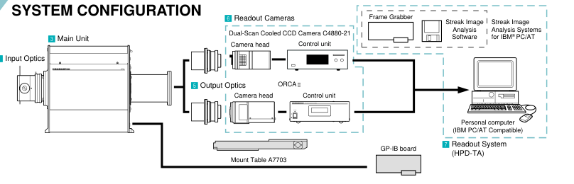
G HPD-TA
The HPD-TA (Temporal Analayzer) is a high-perfomance digital
data acquisition and control system specifically designed to read-
out images from the phosphor screen of the HAMAMATSU
streak camera. It enables precise, quantitative acquisition and
preanalysis of two dimensional streak data that includes photon
counting plus a full range of data correction and calibration
possibilities. The HPD-TA allows the remote control of the
C7700 via GPIB interface. The entire system is controlled
through a powerful and user-friendly application software that
runs on a Microsoft Windows platform
UTILITY
- Line voltage ......................... VA100 V to 120/220 V to 240 C
- Power consumption ................................... Approx. 180 V•A
- Operating temperature ................................. +10 ˚C to +30 ˚C
- Operating humidity ..... Less than 70 % (with no condensation)
Page 4
OPTIONAL
G PIN Photodiode C1083-01
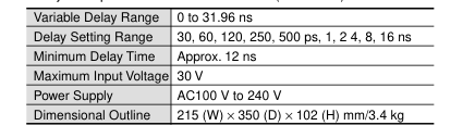
Delay Unit C1097-01 G
Converts low-repetition light pulses to an electronic trigger for streak
This passive delay unit provides convenient timing adjustment with zero jitter. Optional remote GPIB control (C1097-04).
sweep.
| Spectral response | 400 to 1100 nm |
| Rise time | 0.8 ns |
| Power supply | +22.5 V (battery) |
| Dimensional Outline | Head: 100 (W) × 160 to 235 (H) × 50 (D) mm/400 g |
| Power supply unit: 100 (W) × 83(H) × 100 (D) mm/400 g |
DIMENSIONAL OUTLINES (Unit: mm)
G Main Unit (approx. 24.0 kg)
250 ± 1
(C-mount)
106.6 ± 1
285 ± 1
160.5 ± 3
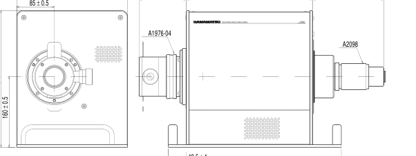
40.5 ± 1
390 ± 1
# IBM is a registered trademark of IBM Co.
ISO 9001 Certificate: 09 105 79045
# Windows is a trademark of Microsoft Corporation in the U.S.A. is a registered trademark of Apple Computer, Inc. # # Product and software package names noted in this documentation are trademarks or registered trademarks of their respective manufacturers. G Subject to local technical requirements and regulations, availability of products included in this promotional material may vary. Please consult with our sales office. G Information furnished by HAMAMATSU is believed to be reliable. However, no responsibility is assumed for possible inaccuracies or omissions. Specifications and external appearance are subject to change without notice.. © 2002 Hamamatsu Photonics K.K.
Homepage Address http://www.hamamatsu.com
HAMAMATSU PHOTONICS K.K., Systems Division 812 Joko-cho, Hamamatsu City, 431-3196, Japan, Telephone: (81)53-431-0124, Fax: (81)53-435-1574, E-mail:export@sys.hpk.co.jp U.S.A. and Canada: Hamamatsu Photonic Systems: 360 Foothill Road, Bridgewater, N.J. 08807-0910, U.S.A., Telephone: (1)908-231-1116, Fax: (1)908-231-0852, E-mail: usa@hamamatsu.com Germany: Hamamatsu Photonics Deutschland GmbH: Arzbergerstr. 10, D-82211 Herrsching am Ammersee, Germany, Telephone: (49)8152-375-0, Fax: (49)8152-2658, E-mail: info@hamamatsu.de
,
France: Hamamatsu Photonics France S.A.R.L.: 8, Rue du Saule Trapu, Parc du Moulin de Massy, 91882 Massy Cedex, France, Telephone: (33)1 69 53 71 00, Fax: (33)1 69 53 71 10, E-mail: infos@hamamatsu.fr United Kingdom: Hamamatsu Photonics UK Limited: 2 Howard Court, 10 Tewin Road, Welwyn Garden City, Hertfordshire, AL7 1BW, U.K., Telephone: (44) 1707-294888, Fax: (44) 1707-325777, E-mail: info@hamamatsu.co.uk North Europe: Hamamatsu Photonics Norden AB: Smidesvägen 12, SE-171-41 Solna, Sweden, Telephone: (46)8-509-031-00, Fax: (46)8-509-031-01, E-mail: info@hamamatsu.se
-
Cat. No. SSCS1049E07
Italy: Hamamatsu Photonics Italia S.R.L.: Strada della Mois, 1/E 20020 Arese (Milano), Italy, Telephone: (39)02-935 81 733, Fax: (39)02-935 81 741, E-mail: info@hamamatsu.it
APR/2002 HPK Created in Japan (PDF)