


 Download PDF
C7247 HAMAMATSU
Document overview
- PDF pages: 4
Technical content
Page 1

DEC. 2000
The C7247 series is a DA type socket assembly designed for 28 mm (1-1/8 inch) diameter side-on and head-on
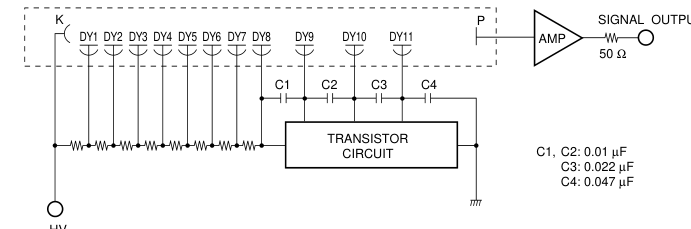
photomultiplier tubes. The C7247 series socket assembly incorporates a voltage-divider circuit and a current-to-voltage
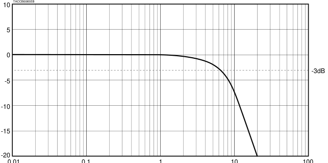
conversion circuit along with an amplifier having a wide bandwidth (0 Hz to 5 MHz).
The C7247 series converts the low-level, high-impedance current of a photomultiplier tube into a low-impedance
voltage output by a factor of 0.3 V/ µA.
Since the C7247 series employs an active voltage-divider circuit, it ensures an excellent DC linearity at low power
consumption.
FEATURES
- Low power consumption
- Low offset voltage
- Wide frequency band
- Compact and light weight
SPECIFICATIONS
| Parameter | C7247 | C7247-01 | Unit |
|---|---|---|---|
| Applicable Photomultiplier Tubes | 28 mm Dia. Head-on | 28 mm Dia. Side-on | – |
| R374, R2228, R5929, R6095, etc | R928, R3788, R3896, R4220, etc | – | |
| MAXIMUM RATINGS Parameter Value Unit | |||
| Input Voltage for Amplifier | ±18 | V dc | |
| Supply Voltage for Divider | -1500 | V dc | |
| Operating Temperature | 0 to +40 | ˚C | |
| Storage Temperature | -15 to +60 | ˚C | |
GENERAL
| Parameter | C7247 | C7247-01 | Unit | |
|---|---|---|---|---|
| Input Voltage for Amplifier | ±12 to ±15a | V dc | ||
| Input Current for Amplifier (at ±15 V) | 12 | mA Typ. | ||
| Recommended Supply Voltage for Divider | -400 to -900 | -300 to -600 | V dc | |
| Divider Current | 219 (at HV=-900 V) | 166 (at HV=-600 V) | µA Typ. | |
| Current to Voltage Conversion Factor | 0.3 | V/µA | ||
| Maximum Output Voltage (with no load resistor) | 10 | V | ||
| Output Voltage (with 50 Ω load resistor) | 3 | V | ||
| Maximum Input Signal Current (at 10 V output, HV=-1000 V with no load resistor) | DC | 33 | µA | |
| Pulse | 33 | µA | ||
| Frequency Bandwidth (-3 dB) | 0 Hz to 5 MHz | – | ||
| Output Impedance | 50 | Ω | ||
| Offset Voltage | ±3 | mV Max. | ||
| Output Noise Voltage | 9 | mV rms. Typ. | ||
| Total Power Consumption (at ±15 V) | 558 (at HV=-900 V) | 460 (at HV=-600 V) | mW Typ. | |
| Weight | 55 | 50 | g Typ. | |
a To be also practicable even with ±5 V of input supply voltage except for narrow output range (2 V max).
Subject to local technical requirements and regulations, availability of products included in this promotional material may vary. Please consult with our sales office. Information furnished by HAMAMATSU is believed to be reliable. However, no responsibility is assumed for possible inaccuracies or omissions. Specifications are subject to change without notice. No patent rights are granted to any of the circuits described herein. ©2000 Hamamatsu Photonics K.K
Page 2
DA-TYPE SOCKET ASSEMBLIES C7247 SERIES
Figure 1. Schematic Diagram
-HV
TACCC0115EB
Figure 2. Frequency Response of Built-in Amplifier
0.01
0.1
100
1
10
FREQUENCY (MHz)
Page 3
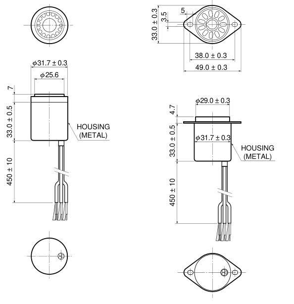
Figure 3. Dimensional Outline (Unit: mm)
C7247
C7247-01
TACCA0197EB
| -HV | SHIELD CABLE 1) |
| SIGNAL OUTPUT | COAX RG-174/U |
| ±15 V | SHIELDED CABLE (COVERING TWISTED PAIR)2) |
RED BLACK GRAY
NOTES: 1) At the end of HV cable, it's possible to attach SHV connector fitting RG-174/U. 2) Connect as follows. Orange Lead ⋅⋅⋅⋅⋅⋅⋅ +15 V White Lead ⋅⋅⋅⋅⋅⋅⋅⋅⋅⋅ -15 V Shield ⋅⋅⋅⋅⋅⋅⋅⋅⋅⋅⋅⋅⋅⋅⋅⋅⋅⋅⋅ GND.
Page 4
DA-TYPE SOCKET ASSEMBLIES C7247 SERIES
OPTIONS
GHOUSING E7718 FOR C7247 (INCLUDING PART #1, 2, 4 AND 5) (Unit: mm)
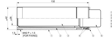
HOUSING 1 MAGNETIC SHIELD CASE 2 PMT 3 O-RINGS 4 4-M2 SCREWS L = 6 5 C7247
[SUGGESTED FIXTURE LAYOUT FOR THE FLANGE]
[HOW TO USE THE HOUSING WITH FLANGE]
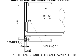
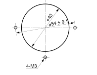
\* THE FLANGE AND O-RING ARE AVAILABLE TO ORDER SEPARATELY AS P/N; A7719.
TACCA0198EA
GFLANGE SET A7709 FOR C7247-01 (INCLUDING PART #1, 4, 5, 6, 8 AND !0) (Unit: mm)
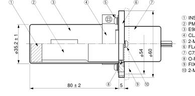
INSULATOR (CUSHION) PMT E989 MAGNETIC SHIELD CASE CLAMPING METAL PARTS 2-M3 SCREWS L = 5 FLANGE C7247-01 O-RING FIXTURE 2-M3 SCREWS L = 5
[SUGGESTED FIXTURE LAYOUT FOR THE FLANGE]
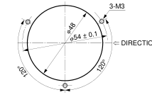
DIRECTION OF INCIDENT LIGHT
TACCA0199EA
HOMEPAGE URL http://www.hamamatsu.com
HAMAMATSU PHOTONICS K.K., Electron Tube Center 314-5, Shimokanzo, Toyooka-village, Iwata-gun, Shizuoka-ken, 438-0193, Japan, Telephone: (81)539/62-5248, Fax: (81)539/62-2205 U.S.A.: Hamamatsu Corporation: 360 Foothill Road, P. O. Box 6910, Bridgewater. N.J. 08807-0910, U.S.A., Telephone: (1)908-231-0960, Fax: (1)908-231-1218 E-mail: usa@hamamatsu.com Germany: Hamamatsu Photonics Deutschland GmbH: Arzbergerstr. 10, D-82211 Herrsching am Ammersee, Germany, Telephone: (49)8152-375-0, Fax: (49)8152-2658 E-mail: info@hamamatsu.de France: Hamamatsu Photonics France S.A.R.L.: 8, Rue du Saule Trapu, Parc du Moulin de Massy, 91882 Massy Cedex, France, Telephone: (33)1 69 53 71 00, Fax: (33)1 69 53 71 10 E-mail: infos@hamamatsu.fr
United Kingdom: Hamamatsu Photonics UK Limited: 2 Howard Court, 10 Tewin Road Welwyn Garden City Hertfordshire AL7 1BW, United Kingdom, Telephone: 44-(0)1707-294888, Fax: 44(0)1707-325777 E-mail: info@hamamatsu.co.uk North Europe: Hamamatsu Photonics Norden AB: Smidesvägen 12, SE-171-41 SOLNA, Sweden, Telephone: (46)8-509-031-00, Fax: (46)8-509-031-01 E-mail: info@hamamatsu.se Italy: Hamamatsu Photonics Italia: S.R.L.: Strada della Moia, 1/E, 20020 Arese, (Milano), Italy, Telephone: (39)02-935 81 733, Fax: (39)02-935 81 741 E-mail: info@hamamatsu.it
TACC1024E02 DEC. 2000 IP Printed in Japan (500)