
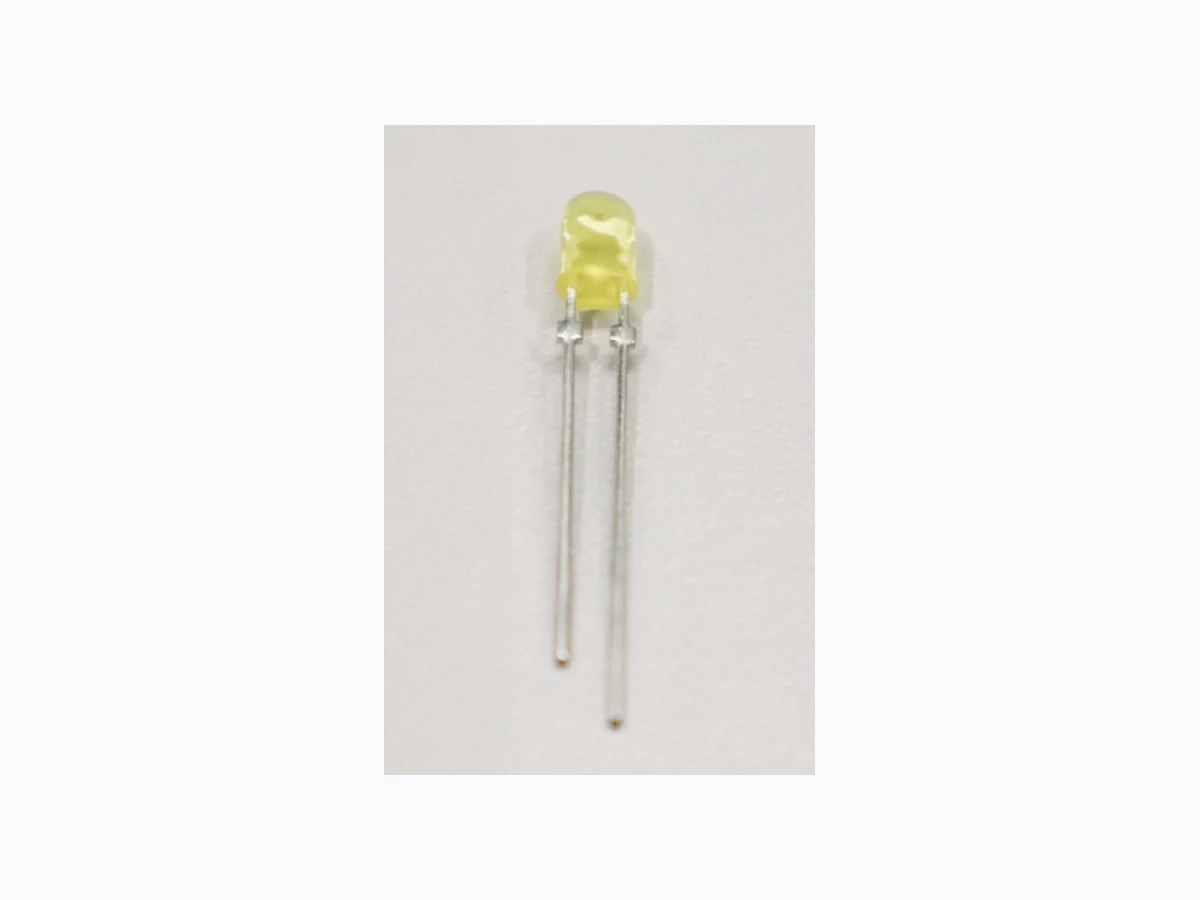
C4SMB-AGY CREE
Document overview
- Manufacturer or author: Provided By www.digicamel.com(FREE DATASHEET DOWNLOAD SITE)
- PDF pages: 9
Technical content
© 2021-2024 Cree LED. The information in this document is subject to change without notice. Cree®, the Cree logo and the Cree LED logo are registered trademarks of Cree LED. CLD-CT1489 REV 3 Screen Master® 4-mm Oval LEDs: C4SMB-AGY PRODUCT DESCRIPTION These oval LEDs are specifically designed for full-color video screens, digital billboards and passenger-information signs. The oval- shaped radiation pattern and high luminous intensity ensure that these devices are excellent for bright sunlight or low power consumption outdoor applications. These lamps are made with an advanced optical-grade epoxy that offers superior high-temperature and high-moisture- resistance performance in outdoor signal and sign applications.The encapsulation resin contains anti-UV material in order to reduce the effects of long-term exposure to direct sunlight.
FEATURES
- Size (mm): 4
- Color and Typical Dominant Wavelength: Amber (591nm)
- Luminous Intensity (mcd) C4SMB-AGY: (1976 - 3885)@20mA
- Lead - Free
- RoHS Compliant
APPLICATIONS
- Electronic Signs & Signals (ESS)
- Full Color Video Screen
- Digital Billboards
- Motorway Signs
- Variable Message Sign (VMS)
- Advertising Signs
- Petrol Signs
SCREEN MASTER ® 4-MM OVAL LED s C4SMB-AGY © 2021-2024 Cree LED. The information in this document is subject to change without notice. Cree®, the Cree logo and the Cree LED logo are registered trademarks of Cree LED. CLD-CT1489 REV 3 ABSOLUTE MAXIMUM RATINGS (T A = 25°C) Items Symbol Absolute Maximum Rating Unit Forward Current IF 50 Note1 mA Peak Forward Current Note2 IFP 200 mA Reverse Voltage VR 5 V Power Dissipation PD 130 mW Operation Temperature Topr -40 ~ +95 °C Storage Temperature Tstg -40 ~ +100 °C Lead Soldering Temperature Tsol Max. 260°C for 3 sec. max. (3 mm from the base of the epoxy bulb) Electrostatic Discharge Classification (MIL-STD-883E) ESD Class 2 Note: 1. For long term performance the drive currents between 10mA and 30mA are recommended. Please contact Cree LED sales representative for more information on recommended drive conditions. 2. Pulse width ≤0.1 msec, duty ≤1/10. TYPICAL ELECTRICAL & OPTICAL CHARACTERISTICS (T A = 25°C) Characteristics Symbol Condition Unit Minimum Typical Maximum Forward Voltage VF IF = 20 mA V 2.1 2.6 Reverse Current IR VR = 5 V μA 100 Dominant Wavelength λD IF = 20 mA nm 584 591 596 Luminous Intensity IV IF = 20 mA mcd 1976 2400 * Continuous reverse voltage can cause LED damage.
SCREEN MASTER ® 4-MM OVAL LED s C4SMB-AGY © 2021-2024 Cree LED. The information in this document is subject to change without notice. Cree®, the Cree logo and the Cree LED logo are registered trademarks of Cree LED. CLD-CT1489 REV 3 INTENSITY BIN LIMIT Amber (20 mA) - C4SMB-AGY Bin Code Min.(mcd) Max.(mcd) U4 1976 2130 V1 2130 2347 V2 2347 2564 V3 2564 2781 V4 2781 3000 W1 3000 3295 W2 3295 3590 W3 3590 3885 * Tolerance of measurement of luminous intensity is ±15% COLOR BIN LIMIT Amber (20mA) - C4SMB-AGY Bin Code Min.(nm) Max.(nm) A2 584 587 A3 587 590 A4 590 593 A5 593 596 * Tolerance of measurement of dominant wavelength is ±1 nm.
SCREEN MASTER ® 4-MM OVAL LED s C4SMB-AGY © 2021-2024 Cree LED. The information in this document is subject to change without notice. Cree®, the Cree logo and the Cree LED logo are registered trademarks of Cree LED. CLD-CT1489 REV 3 ORDER CODE TABLE C4SMB-AGY Color Kit Number Luminous Intensity (mcd) Dominant Wavelength Package Min. Max. Color Bin Min. (nm) Color Bin Max. (nm) Amber C4SMB-AGY-CU4W3251 1976 3885 A2 584 A5 596 Bulk Amber C4SMB-AGY-CU44Q341 Any 4 consecutive sub-bins: U4(1976) - W1(3295) A3 587 A4 593 Bulk Amber C4SMB-AGY-CV14Q341 Any 4 consecutive sub-bins: V1(2130) - W2(3590) A3 587 A4 593 Bulk Amber C4SMB-AGY-CU4W3252 1976 3885 A2 584 A5 596 Ammo Amber C4SMB-AGY-CU44Q342 Any 4 consecutive sub-bins: U4(1976) - W1(3295) A3 587 A4 593 Ammo Amber C4SMB-AGY-CV14Q342 Any 4 consecutive sub-bins: V1(2130) - W2(3590) A3 587 A4 593 Ammo Notes:
- The above kit numbers represent order codes that include multiple intensity-bin and color-bin codes. Only one intensity-bin code and one color-bin code will be shipped on each bulk. Single intensity-bin code and single color-bin codes will not be orderable.
- Please refer to the HB LED Lamp Reliability Test Standards document for reliability test conditions.
- Please refer to the HB LED Lamp Soldering & Handling document for information about how to use this LED product safely.
SCREEN MASTER ® 4-MM OVAL LED s C4SMB-AGY © 2021-2024 Cree LED. The information in this document is subject to change without notice. Cree®, the Cree logo and the Cree LED logo are registered trademarks of Cree LED. CLD-CT1489 REV 3 GRAPHS The data below are collected from statistical figures that do not necessarily correspond to the actual parameters of each single LED. Hence, these data will be changed without further notice. FIG.5 RELATIVE LUMINOUS INTENSITY VS. (RELATIVE LUMINOUS INTENSITY) WAVELENGTH. WL(nm) 80% 20% 40% 60% 100% 700300 500400 600 800 900 FIG.2 RELATIVE LUMINOUS INTENSITY VS. FORWARD CURRENT IF(mA)VF(V) 3.4 FORWARD VOLTAGE. FIG.1 FORWARD CURRENT VS. 20.0 2.2 0.0 2.8 4.0 4.6 5.0 60.0 40.0 80.0 100.0 IF (mA) 1.6 0.0 1.0 4.0 2.0 3.0 5.0 300.0 15 6045 75 90 -10 VS. REVERSE VOLTAGE. FIG.3 REVERSE CURRENT -50 Vr(V) -30-40 -20 -40 Ir(uA) -50 -30 -20 -10 0-60 IF(mA) FIG.4 MAXIMUM FORWARD DC CURRENT VS AMBIENT TEMPERATURE (Tjmax=105 C) 100 4020 8060 100 1200 Ta( C) (RELATIVE LUMINOUS INTENSITY) FIG.6 FAR FIELD PATTERN (RELATIVE LUMINOUS INTENSITY) -90 -60 -30 0 0.5 1.0 0.5 1.0 2010 H-H V-V
SCREEN MASTER ® 4-MM OVAL LED s C4SMB-AGY © 2021-2024 Cree LED. The information in this document is subject to change without notice. Cree®, the Cree logo and the Cree LED logo are registered trademarks of Cree LED. CLD-CT1489 REV 3 MECHANICAL DIMENSIONS All dimensions are in mm. Tolerance is ±0.25 mm unless otherwise noted. An epoxy meniscus may extend about 1.5 mm down the leads. Burr around bottom of epoxy may be 0.5 mm max. NOTES Lead Frame Materials Ag-plated and Lead-free Solder-plated iron. RoHS Compliance The levels of RoHS restricted materials in this product are below the maximum concentration values (also referred to as the threshold limits) permitted for such substances, or are used in an exempted application, in accordance with EU Directive 2011/65/EC (RoHS2), as implemented January 2, 2013. RoHS Declarations for this product can be obtained from your Cree LED representative or from the Product Ecology section of the Cree LED website. Vision Advisory WARNING: Do not look at an exposed lamp in operation. Eye injury can result.
SCREEN MASTER ® 4-MM OVAL LED s C4SMB-AGY © 2021-2024 Cree LED. The information in this document is subject to change without notice. Cree®, the Cree logo and the Cree LED logo are registered trademarks of Cree LED. CLD-CT1489 REV 3 KIT NUMBER SYSTEM Cree LED lamps are tested and sorted into performance bins. A bin is specified by ranges of color, forward voltage, and brightness. Sorted LEDs are packaged for shipping in various convenient options. Cree LEDs are sold by order codes in combinations of bins called kits. Order codes are configured in the following manner: CCCCC-DXG -XHHKKMNT D - Color CCCCC - Product Series G - Option S : S tandof f N : N o S tand o f f B : Black F ace W : W h i te Fac e A : Black Body E: Iron Lead Frame without standoff F : Iron Lead Frame with Standoff Y: Tin free Stopper/Iron Lead Frame X: Tin free No Stopper/Iron Lead Frame M - Min. W avele ngth/Chromaticit y Range R efe r to o r d er co de t a b l e N - Max. W avel ength/Chromaticity Range R : S e l ect 1 hue fro m 4 hue bi n s S : S e l ect 1 hue fro m 3 h ue bi n s T : Select 1 hue f r o m 2 h u e bins U : S e l ect 2 hue fro m 4 hue bi n s V : S e l ect 2 hue fro m 3 h ue bi n s T - Packaging T ype 1 : B u l k P a c k 2 : Ammo Pack 3 : Ta p e & Reel ( R o ll P ack ) 4 : T u b e Pac k HH - Minimu m I ntensity Bin R efe r to o rder code tabl e KK - Maximum Int ensity Bin R efe r to o rder code tabl e * Please contact our sal es representati ve for orderi ng i nform ation .
SCREEN MASTER ® 4-MM OVAL LED s C4SMB-AGY © 2021-2024 Cree LED. The information in this document is subject to change without notice. Cree®, the Cree logo and the Cree LED logo are registered trademarks of Cree LED. CLD-CT1489 REV 3 SOLDERING GUIDELINES The LED soldering specification is shown below(suitable for both leaded solder & lead-free solder): Manual Soldering Solder Dipping Soldering iron 35 W max Preheat 110 ºC max Temperature 300 ºC max Preheat time 60 seconds max Solder-bath temperature 260 ºC Max Soldering time 3 seconds max Dipping time 5 seconds max Position Not less than 3 mm from the base of the package. Position Not less than 3 mm from the base of the package.
- Manual soldering onto the PCB is not recommended because soldering time is uncontrollable.
- The recommended wave soldering is as below: 10 20 30 40 50 60 70 80 90 100 110 120 150 100 300 250 200
50 Temperature ºC
Times (sec) laminar wave Fluxing Preheat
- Do not apply any stress to the LED package, particularly when heated.
- Only bottom preheat is suggested & should not preheat on top in order to reduce thermal stress experienced by the LEDs.
- The LEDs must not be re used once they have been extracted from PCB.
- After soldering the LEDs, the package should be protected from mechanical shock or vibration until the LEDs have reached 40 ºC or below.
- Precautions must be taken as mechanical stress on the LEDs may be caused by PCB warpage or from the clinching and cutting of the LED leads.
- When it is necessary to clam the LEDs during soldering, it is important to ensure no mechanical stress is exerted on the LEDs.
- Cut the LED lead at normal room temperature. Lead cutting at high temperature may cause failure of the LEDs.
- Please refer to the HB LED Lamp Soldering & Handling document for information about how to use this LED product safely.
SCREEN MASTER ® 4-MM OVAL LED s C4SMB-AGY © 2021-2024 Cree LED. The information in this document is subject to change without notice. Cree®, the Cree logo and the Cree LED logo are registered trademarks of Cree LED. CLD-CT1489 REV 3 PACKAGING
- The LEDs are packed in cardboard boxes after packaging in normal or anti-electrostatic bags.
- Cardboard boxes will be used to protect the LEDs from mechanical shock during transportation.
- The boxes are not water resistant, and they must be kept away from water and moisture.
- Max 1000 pcs per bulk and Max 3000 pcs per ammo. Bulk Pack Packaging Type: Ammo Pack Packaging Type: 10 bags/carton Label A XXXXXXXXXXX (anti-electrostatic bag) xxx xxx