

 Download PDF
C4900 HAMAMATSU
Document overview
- PDF pages: 2
Technical content
Page 1

PATENT
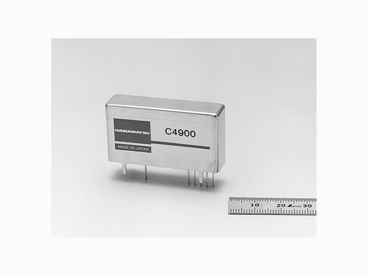
The C4900 series are compact PC–board mountable high voltage power supplies, especially designed for photomultiplier tubes. The design offers better performance and improved fail–safe protection. The C4900 and–01 output negative polarity and the C4900–50 and –51 output positive polarity high voltages.
FEATURES
Compact and Lightweight High stability Low Power Consumption Fast Response Wide Variable Output Range Ample Protective and Fail–safe Functions
SPECIFICATIONS
| Parameter | C4900 | C4900-01 | C4900-50 | C4900-51 | Unit | |
|---|---|---|---|---|---|---|
| Input Voltage Range | +15 ± 1 | +12 ± 0.5 | +15 ± 1 | +12 ± 0.5 | V | |
| Input Current a | with no load | 14 | 15 | 14 | 15 | mA (Typ.) |
| with full load | 90 | 95 | 90 | 95 | ||
| Variable Output Range | 0 to –1250 | 0 to +1250 | V | |||
| Specification Guaranteed Output Voltage Range | –200 to –1250 | +200 to +1250 | V | |||
| Output Current b | 0.6 | 0.5 | 0.6 | 0.5 | mA (Max.) | |
| Line Regulation against ±1 V or 0.5 V Change b | ± 0.01 | % (Typ.) | ||||
| Load Regulation against 0 % to 100 % Load Change a | ± 0.01 | % (Typ.) | ||||
| Ripple / Noise (p-p) b | 0.007 | % (Typ.) | ||||
| Output Voltage Controlling Modes | By external controlling voltage (0 V to +5 V) or external potentiometer (50 kΩ ± 2.5 kΩ) | |||||
| Controlling Voltage Input Impedance | 80 | kΩ (Typ.) | ||||
| Reference Voltage Output | +5.13 (with 50 kΩ external potetiometer) | V (Typ.) | ||||
| Output Voltage Setting (Absolute value) | (Controlling voltage × 250) ± 0.5 % | V (Typ.) | ||||
| Output Voltage Rise Time (0 % 99 %) b | 50 | ms (Typ.) | ||||
| Temperature Coefficient b | ± 0.01 | %/°C (Typ.) | ||||
| Operating Temperature Range b | 0 to +50 | °C | ||||
| Storage Temperature Range | -20 to +70 | °C | ||||
| Dimensions (W × H × D) | 46 × 24 × 12 | mm | ||||
| Weight | 31 | g | ||||
| Protective Functions | Units protected against reversed power input, reversed/excessive controlling voltage input, continuous overloading/short circuit in output | |||||
a At Maximum Output Voltage.
b At Maximum Output Voltage and Current.
Subject to local technical requirements and regulations, availability of products included in this promotional material may vary. Please consult with our sales office. Information furnished by HAMAMATSU is believed to be reliable. However, no responsibility is assumed for possible inaccuracies or omissions. Specifications are subject to change without notice. No patent rights are granted to any of the circuits described herein. ©2001 Hamamatsu Photonics K.K
Page 2
HIGH VOLTAGE POWER SUPPLY UNIT C4900 SERIES
Figure 1: Output Voltage Controlling
BY EXTERNAL VOLTAGE
BY EXTERNAL POTENTIOMETER
| q w e r t y | |
| or +12V | NO CONNECTION (IC) 0 V to +5 V* LOAD |
| q w e r t y | |
| or +12 V | MIN MAX 50 kΩ LOAD |
+15 V or +12V
+15 V or +12 V
\* The instability in the external controlling voltage should be minimized as it directly affects the output voltage quality.
PIN ASSIGNMENT q +15 V or +12 V IN w GND 1 (Input/Output GND) e GND 2 (Controlling Voltage GND) r HV ADJ (Controlling Voltage Input) t Vref OUT (Reference Voltage Output : 5.13V Typ.) y HV OUT The housing is internally connected to pin w. Pins w and e are internally connected.
TACCC0049ED
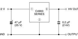
Figure 3: Example of Ripple/Noise Reduction Circuit
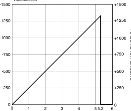
Figure 2: Output Voltage Controlling Characteristic
(C4900, -01)
(C4900-50, -51)
TACCB0043EA
+15 V or +12 V
INPUT GND
OUTPUT GND
\*The ripple/noise can be halved by adding capacitors as illustrated above.
CONTROLLING VOLTAGE (V)
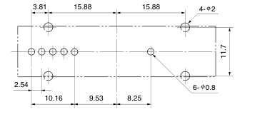
Figure 4: Dimensional Outline (Unit: mm)
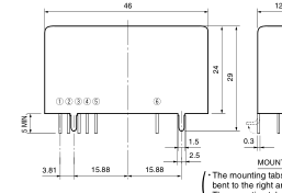
TACCC0099EB
Drilling Data for PC Board
(Soldering Face)
MOUNTING TABS
The mounting tabs are solderable. )
bent to the right angle only once
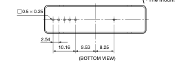
TACCA0159EB
TACCA0157EB
\*PATENT: USA No.5548502, 5568343 JAPAN: No.2758552, 2784136 EUROPE: No.641066, 649222
HOMEPAGE URL http://www.hamamatsu.com
HAMAMATSU PHOTONICS K.K., Electron Tube Center
314-5, Shimokanzo, Toyooka-village, Iwata-gun, Shizuoka-ken, 438-0193, Japan, Telephone: (81)539/62-5248, Fax: (81)539/62-2205 U.S.A.: Hamamatsu Corporation: 360 Foothill Road, P. O. Box 6910, Bridgewater. N.J. 08807-0910, U.S.A., Telephone: (1)908-231-0960, Fax: (1)908-231-1218 E-mail: usa@hamamatsu.com Germany: Hamamatsu Photonics Deutschland GmbH: Arzbergerstr. 10, D-82211 Herrsching am Ammersee, Germany, Telephone: (49)8152-375-0, Fax: (49)8152-2658 E-mail: info@hamamatsu.de France: Hamamatsu Photonics France S.A.R.L.: 8, Rue du Saule Trapu, Parc du Moulin de Massy, 91882 Massy Cedex, France, Telephone: (33)1 69 53 71 00, Fax: (33)1 69 53 71 10 E-mail: infos@hamamatsu.fr
United Kingdom: Hamamatsu Photonics UK Limited: 2 Howard Court, 10 Tewin Road Welwyn Garden City Hertfordshire AL7 1BW, United Kingdom, Telephone: 44-(0)1707-294888, Fax: 44(0)1707-325777 E-mail: info@hamamatsu.co.uk North Europe: Hamamatsu Photonics Norden AB: Smidesvägen 12, SE-171-41 SOLNA, Sweden, Telephone: (46)8-509-031-00, Fax: (46)8-509-031-01 E-mail: info@hamamatsu.se
TACC1013E02
Italy: Hamamatsu Photonics Italia: S.R.L.: Strada della Moia, 1/E, 20020 Arese, (Milano), Italy, Telephone: (39)02-935 81 733, Fax: (39)02-935 81 741 E-mail: info@hamamatsu.it
MAY. 2001 IP Printed in Japan (500)