
C3M0280090D WOLFSPEED
Document overview
- Manufacturer or author: Provided By www.digicamel.com(free datasheet download site)
- PDF pages: 11
Technical content
Features
- C3M SiC MOSFET technology
- High blocking voltage with low On-resistance
- High speed switching with low capacitances
- Fast intrinsic diode with low reverse recovery (Qrr)
- Halogen free, RoHS compliant Benefits
- Higher system efficiency
- Reduced cooling requirements
- Increased power density
- Increased system switching frequency
Applications
- Renewable energy
- Lighting
- High voltage DC/DC converters
- Telecom Power Supplies
- Induction Heating Package Part Number Package Marking C3M0280090D TO-247-3 C3M0280090 Maximum Ratings (TC = 25 ˚C unless otherwise specified) Symbol Parameter Value Unit Test Conditions Note VDSmax Drain - Source Voltage 900 V VGS = 0 V, ID = 100 μA VGSmax Gate - Source Voltage (dynamic) -8/+19 V AC (f >1 Hz) Note: 1 VGSop Gate - Source Voltage (static) -4/+15 V Static Note: 2 ID Continuous Drain Current 10.2 A VGS = 15 V, TC = 25˚C Fig. 19
6.8 VGS = 15 V, TC = 100˚C
ID(pulse) Pulsed Drain Current 22 A Pulse width tP limited by Tjmax Fig. 22 PD Power Dissipation 45 W TC=25˚C, TJ = 150 ˚C Fig. 20 TJ , Tstg Operating Junction and Storage Temperature -55 to +150 ˚C TL Solder Temperature 260 ˚C 1.6mm (0.063”) from case for 10s Md Mounting Torque 1 8.8 Nm lbf-in M3 or 6-32 screw Note (1): When using MOSFET Body Diode VGSmax = -4V/+19V Note (2): MOSFET can also safely operate at 0/+15 V
C3M0280090D Rev. 2, 09-2021 Electrical Characteristics (TC = 25˚C unless otherwise specified) Symbol Parameter Min. Typ. Max. Unit Test Conditions Note V(BR)DSS Drain-Source Breakdown Voltage 900 V VGS = 0 V, ID = 100 μA VGS(th) Gate Threshold Voltage 1.8 2.7 3.5 V VDS = VGS, ID = 1.2 mA Fig. 11 2.2 V VDS = VGS, ID = 1.2 mA, TJ = 150ºC IDSS Zero Gate Voltage Drain Current 1 100 μA VDS = 900 V, VGS = 0 V IGSS Gate-Source Leakage Current 10 250 nA VGS = 15 V, VDS = 0 V RDS(on) Drain-Source On-State Resistance 320 360 mΩ VGS = 15 V, ID = 7.5 A Fig. 4, 5, 6416 VGS = 15 V, ID = 7.5 A, TJ = 150ºC gfs Transconductance 3.6 S VDS= 15 V, IDS= 7.5 A Fig. 7 3.6 VDS= 15 V, IDS= 7.5 A, TJ = 150ºC Ciss Input Capacitance 204 pF VGS = 0 V, VDS = 600 V f = 1 MHz VAC = 25 mV Fig. 17, 18Coss Output Capacitance 26 Crss Reverse Transfer Capacitance 3 Eoss Coss Stored Energy 5.5 μJ Fig. 16 EON Turn-On Switching Energy (Body Diode FWD) 80 μJ VDS = 400 V, VGS = -4 V/15 V, ID = 7.5 A, RG(ext) = 2.5Ω, L= 201 μH, TJ = 150ºC Fig. 26, Note 3EOFF Turn Off Switching Energy (Body Diode FWD) 6 td(on) Turn-On Delay Time 5.3 ns VDD = 400 V, VGS = -4 V/15 V ID = 7.5 A, RG(ext) = 2.5 Ω, Timing relative to VDS Inductive load Fig. 27, Note 3 tr Rise Time 25 td(off) Turn-Off Delay Time 8.5 tf Fall Time 6.4 RG(int) Internal Gate Resistance 23.5 Ω f = 1 MHz, VAC = 25 mV Qgs Gate to Source Charge 3.0 nC VDS = 400 V, VGS = -4 V/15 V ID = 7.5 A Per IEC60747-8-4 pg 21 Fig. 12Qgd Gate to Drain Charge 2.9 Qg Total Gate Charge 9.7 Reverse Diode Characteristics (TC = 25˚C unless otherwise specified) Symbol Parameter Typ. Max. Unit Test Conditions Note VSD Diode Forward Voltage 4.8 V VGS = -4 V, ISD = 4 A Fig. 8, 9, 104.4 V VGS = -4 V, ISD = 4 A, TJ = 150 °C IS Continuous Diode Forward Current 9 A VGS = -4 V Note 1 IS, pulse Diode pulse Current 22 A VGS = -4 V, pulse width tP limited by Tjmax Note 1 trr Reverse Recover time 24 ns VGS = -4 V, ISD = 7.5 A, VR = 400 V dif/dt = 775 A/µs, TJ = 150 °C Note 1Qrr Reverse Recovery Charge 74 nC Irrm Peak Reverse Recovery Current 4 A Thermal Characteristics Symbol Parameter Max. Unit Test Conditions Note RθJC Thermal Resistance from Junction to Case 2.8 °C/W Fig. 21 RθJA Thermal Resistance From Junction to Ambient 40 Note (3): Turn-off and Turn-on switching energy and timing values measured using SiC MOSFET Body Diode
Figure 29. Clamped Inductive Switching Test Circuit Note (3): Turn-off and Turn-on switching energy and timing values measured using SiC MOSFET Body Diode as shown above.
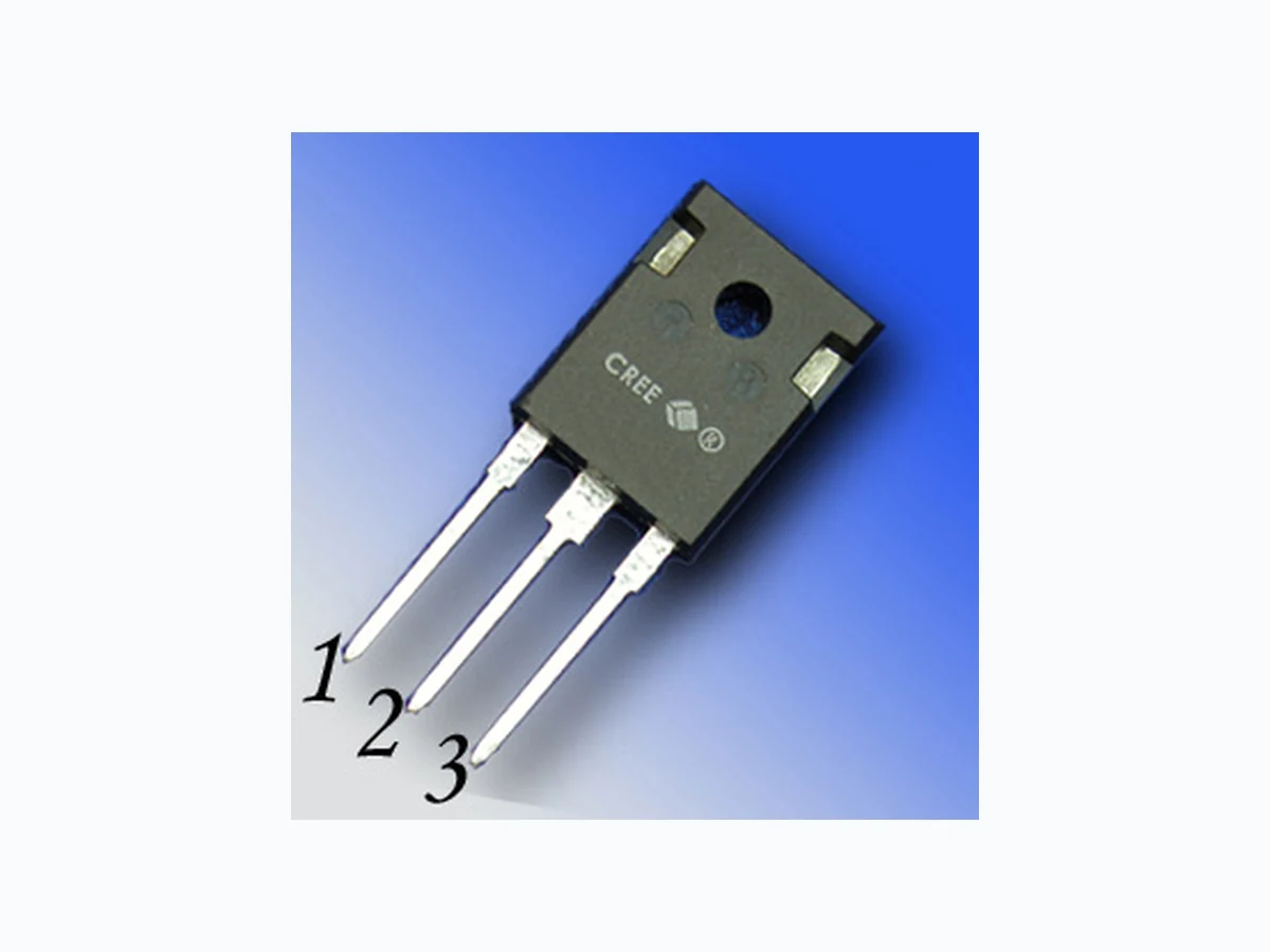
C3M0280090D Rev. 2, 09-2021 NOTE ; 1. ALL METAL SURFACES: TIN PLATED,EXCEPT AREA OF CUT 2. DIMENSIONING & TOLERANCEING CONFIRM TO ASME Y14.5M-1994. 3. ALL DIMENSIONS ARE IN MILLIMETERS. ANGLES ARE IN DEGREES. 4. THIS DRAWING WILL MEET ALL DIMENSIONS REQUIREMENT OF JEDEC outlines TO-247 AD. 5. DIMENSION DO NOT INCLUDE BURR OR MOLD FLASH. 1 - GATE 2 - DRAIN (COLLECTOR) 3 - SOURCE (EMITTER) 4 - DRAIN (COLLECTOR) TITLE: SHEET COMPANY ASE WEIHAI
1 OF 3
DWG NO. 98WHP03165A A Aug.04, 2020 TO-247 3LD ASE Advanced Semiconductor Engineering Weihai, Inc. 1 2 3 Package Dimensions Package TO-247-3
C3M0280090D Rev. 2, 09-2021 Recommended Solder Pad Layout TO-247-3 A b c D E e N L Q S T W X 4.83 5.21 .190 .205 2.29 2.54 .090 .100 1.91 2.16 .075 .085 1.07 1.33 .042 .052 1.91 2.41 .075 .095 2.87 3.38 .113 .133 0.55 0.68 .022 .027 20.80 21.10 .819 .831 16.25 17.65 .640 .695 0.95 1.25 .037 .049 15.75 16.13 .620 .635 13.10 14.15 .516 .557 3.68 5.10 .145 .201 1.00 1.90 .039 .075 12.38 13.43 .487 .529 5.44 BSC .214 BSC 3 3 19.81 20.32 .780 .800 4.10 4.40 .161 .173 3.51 3.65 .138 .144 5.49 6.00 .216 .236 6.04 6.30 .238 .248 17.5° REF. 3.5° REF. 4° REF. TITLE: SHEET COMPANY ASE WEIHAI
2 OF 3
DWG NO. 98WHP03165A A Aug.04, 2020 TO-247 3LD ASE Advanced Semiconductor Engineering Weihai, Inc. Package Dimensions Package TO-247-3
C3M0280090D Rev. 2, 09-2021 Copyright © 2021 Cree, Inc. All rights reserved. The information in this document is subject to change without notice. Cree, the Cree logo, and Zero Recovery are registered trademarks of Cree, Inc. Cree, Inc.
4600 Silicon Drive
Durham, NC 27703 USA Tel: +1.919.313.5300 Fax: +1.919.313.5451 www.wolfspeed.com/power
- RoHS Compliance The levels of RoHS restricted materials in this product are below the maximum concentration values (also referred to as the threshold limits) permitted for such substances, or are used in an exempted application, in accordance with EU Directive 2011/65/ EC (RoHS2), as implemented January 2, 2013. RoHS Declarations for this product can be obtained from your Cree representative or from the Product Documentation sections of www.cree.com.
- REACh Compliance REACh substances of high concern (SVHCs) information is available for this product. Since the European Chemical Agency (ECHA) has published notice of their intent to frequently revise the SVHC listing for the foreseeable future,please contact a Cree represen- tative to insure you get the most up-to-date REACh SVHC Declaration. REACh banned substance information (REACh Article 67) is also available upon request.
- This product has not been designed or tested for use in, and is not intended for use in, applications implanted into the human body nor in applications in which failure of the product could lead to death, personal injury or property damage, including but not limited to equipment used in the operation of nuclear facilities, life-support machines, cardiac defibrillators or similar emergency medical equipment, aircraft navigation or communication or control systems, air traffic control systems. Notes Related Links
- SPICE Models: http:/ /wolfspeed.com/power/tools-and-support
- SiC MOSFET Isolated Gate Driver reference design: http:/ /wolfspeed.com/power/tools-and-support
- SiC MOSFET Evaluation Board: http:/ /wolfspeed.com/power/tools-and-support