

 Download PDF
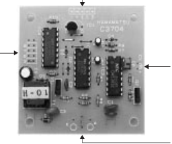
C3704 HAMAMATSU
Document overview
- PDF pages: 2
Technical content
Page 1
UV TRON® DRIVING CIRCUIT
C3704 SERIES
Compact, Lightweight, Low Current Consumption, Low Cost
Operates as High Sensitivity UV Sensor with UV TRON
Suitable for Flame Detectors and Fire Alarms
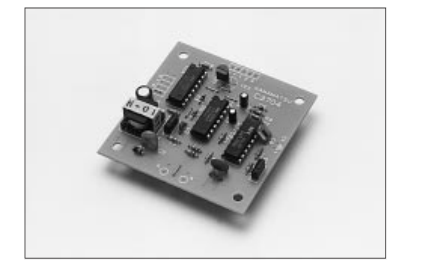
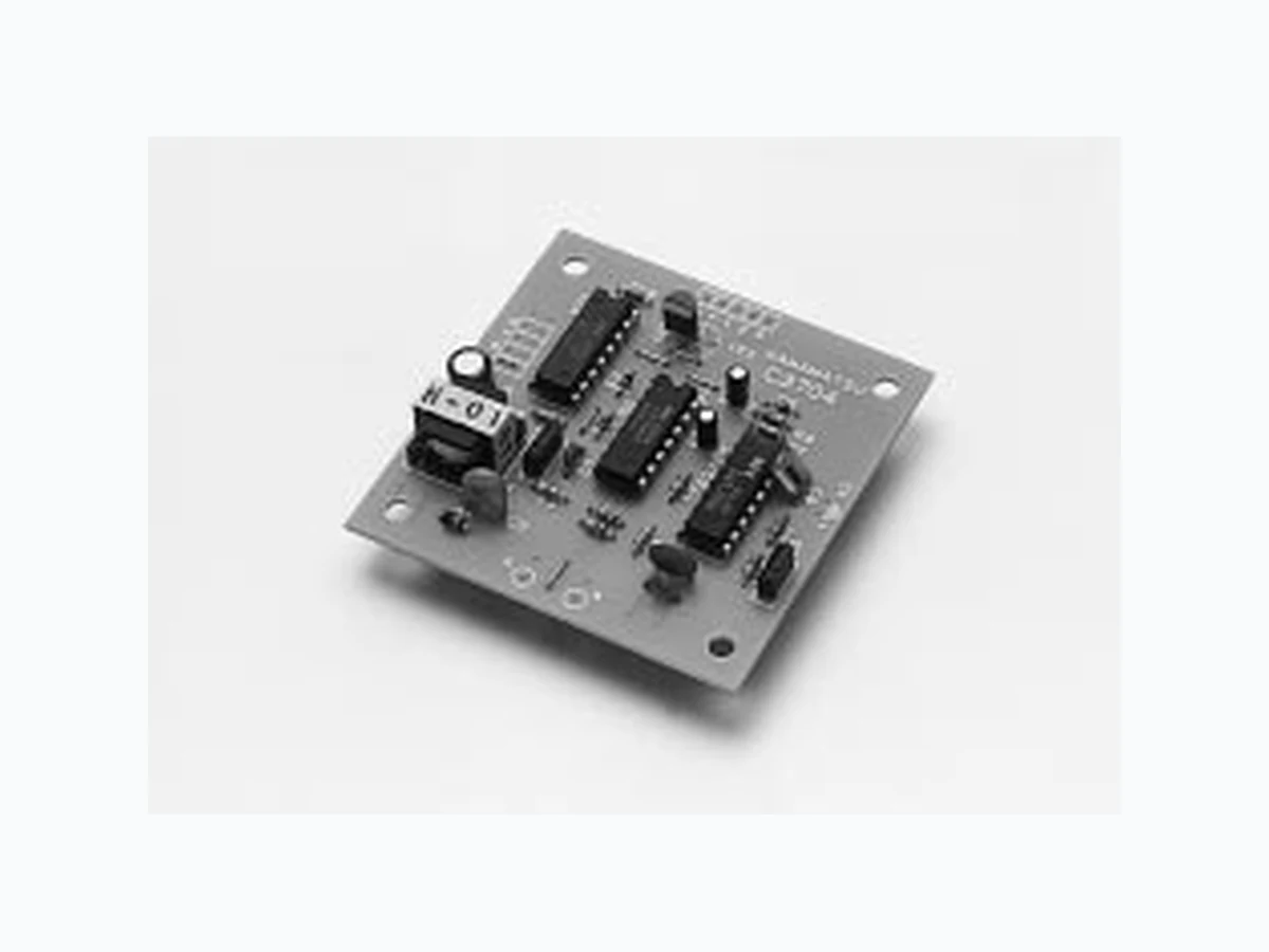
Hamamatsu C3704 series UV TRON driving circuits are low current consuming, signal processing circuits for the UV TRON, well known as a high sensitivity ultraviolet detecting tube. The C3704 series can be operated as a UV sensor by connecting the UV TRON and applying DC low voltage, as they have both a highvoltage power supply and a signal processing circuit on the same printed circuit board. Since background discharges of the UV TRON caused by natural excitation lights (such as a cosmic ray, scattered sunlight, etc.) can be cancelled in the signal processing circuit, the output signals from the C3704 series can be used without errors. When the high sensitivity sensor “UV TRON R2868” (sold
separately) is used, the flame from a cigarette lighter (flame length: 25mm) can be detected even from a distance of more than 5m.
APPLICATIONS
G Flame detectors for gas and oil lighters
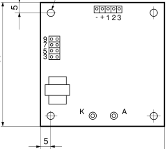
Figure 1: Dimensional Outline (Unit : mm)
G Fire alarms
4- 3.5
G Combustion monitors for burners G Electric spark detector
G UV photoelectric counter
SPECIFICATIONS
Dimensional outline ..................................................... Figure 1 Weight ................................................................... Approx. 20g Output signal ....... Open collector Output (50 V, 100 mA Max.)
10 ms width pulse output (Note : 1)
UV TRON supply voltage .......................... DC 350 V (Note : 2) Quenching time ................................................. Approx. 50 ms Operating temperature ......................................... -10 to +50°C
(with no condensation)
Suitable UV TRON ............... Low voltage operation UV TRON
60
(such as R2868)
| C3704 | C3704-02 | C3704-03 | |
| Input Voltage | 10 to 30 Vdc | 5Vdc ± 5% | 6 to 9 Vdc |
| Current consumption | 3 mA Max. | 300µA Max. | 300µA Max. |
<Top View>
Note 1: The output pulse width can be extended up to about 100s by adding a capacitor to the circuit board. Note 2: Since the output impedance of this power supply is extremely high, an
<Side View>
ordinary voltmeter cannot be used. Use a voltmeter that has an input
TPT A0024EA
impedance of more than 10 GΩ.
Subject to local technical requirements and regulations, availability of products included in this promotional material may vary. Please consult with our sales office. Information furnished by HAMAMATSU is believed to be reliable. However, no responsibility is assumed for possible inaccuracies or omissions. Specifications are subjected to change without notice. No patent rights are granted to any of the circuits described herein. © 1997 Hamamatsu Photonics K. K.
Page 2
UV TRON® DRIVING CIRCUIT C3704 SERIES
Figure 2: Schematic Diagram
UV TRON (SOLD SEPARATELY)
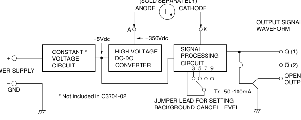
Figure 3: Method of Connection
L
JUMPER LEAD FOR SETTING BACKGROUND CANCEL LEVEL
This background cancel circuit outputs signal pulses of 10ms width only when 3 to 9 pulses enter the circuit with a time interval of 2 seconds or less from the UV TRON. Cancel level can be set in 4 steps (number of pulses: 3, 5, 7, 9) by this jumper lead. Connect to “3” for general use. When using where much natural excitation light is present, set the cancel level at a higher step (5, 7, 9).
5V Q GND
5V Q GND 10 ms (Note 4)
OPEN COLLECTOR OUTPUT (3)
TPT C0004EA
POWER SUPPLY INPUT AND SIGNAL OUTPUT POINT – : GND + : POWER SUPPLY INPUT 1 : SIGNAL OUTPUT Q
(Note 3)
2 : SIGNAL OUTPUT Q 3 : OPEN COLLECTOR OUTPUT
Cx : POINT FOR ADDING A CAPACITOR TO EXTEND OUTPUT PULSE WIDTH
(Note 4)
CONNECTING POINT OF UV TRON A : Connecting Anode of UV TRON K : Connecting Cathode of UV TRON
Note 3: No load can be driven by an output from points “1” and “2” because these signals are output from the only C-MOS IC directly. When a load such as a buzzer and a relay is connected to this circuit, it should be connected to the point open collector output. The transistor ratings of the open collector is 50V, 100mA. Be careful not to exceed the ratings.
Note 4: The output pulse width is set to 10ms at shipping. If the pulse width needs to be extended, add a capacitor to this point. (When using an electrolytic condenser, make sure the polarity is correct.)
1s, CX=10 µF : Pulse Width 10s
e.g. CX = 1 µF: Pulse Width
G A model equipped with a flame sensor (R2868) is also available.
HAMAMATSU PHOTONICS K.K., Electron Tube Center 314-5, Shimokanzo, Toyooka-village, Iwata-gun, Shizuoka-ken, 438-0193, Japan, Telephone: (81)539/62-5248, Fax: (81)539/62-2205, Telex: 4225-186HAMAHQ U.S.A.: Hamamatsu Corporation: 360 Foothill Road, Bridgewater, N.J. 08807-0910, U.S.A., Telephone: (1)908-231-0960, Fax: (1)908-231-1218 Germany: Hamamatsu Photonics Deutschland GmbH: Arzbergerstr. 10, D-82211 Herrsching am Ammersee, Germany, Telephone: (49)8152-375-0, Fax: (49)8152-2658 France: Hamamatsu Photonics France S.A.R.L.: 8, Rue du Saule Trapu, Parc du Moulin de Massy, 91882 Massy Cedex, France, Telephone: (33)1 69 53 71 00, Fax: (33)1 69 53 71 10
United Kingdom: Hamamatsu Photonics UK Limited: Lough Point, 2 Gladbeck Way, Windmill Hill, Enfield, Middlesex EN2 7JA, United Kingdom, Telephone: (44)181-367-3560, Fax: (44)181-367-6384 North Europe: Hamamatsu Photonics Norden AB: Färögatan 7, S-164-40 Kista, Sweden, Telephone: (46)8-703-29-50, Fax: (46)8-750-58-95
TPT1007E01
Italy: Hamamatsu Photonics Italia S.R.L.: Via Della Moia, 1/E 20020 Arese, (Milano), Italy, Telephone: (39)2-935 81 733, Fax: (39)2-935 81 741
JUL.1997 CR Created in Japan