
C2D20120 ETC1
Document overview
- Manufacturer or author: Provided By www.digicamel.com(FREE DATASHEET DOWNLOAD SITE)
- PDF pages: 5
Technical content
Features
1200-Volt Schottky Rectifier Zero Reverse Recovery Zero Forward Recovery High-Frequency Operation Temperature-Independent Switching Behavior Extremely Fast Swtitching Positive Temperature Coefficient on VF Benefits Replace Bipolar with Unipolar Rectifiers Essentially No Switching Losses Higher Efficiency Reduction of Heat Sink Requirements Parallel Devices Without Thermal Runaway
Applications
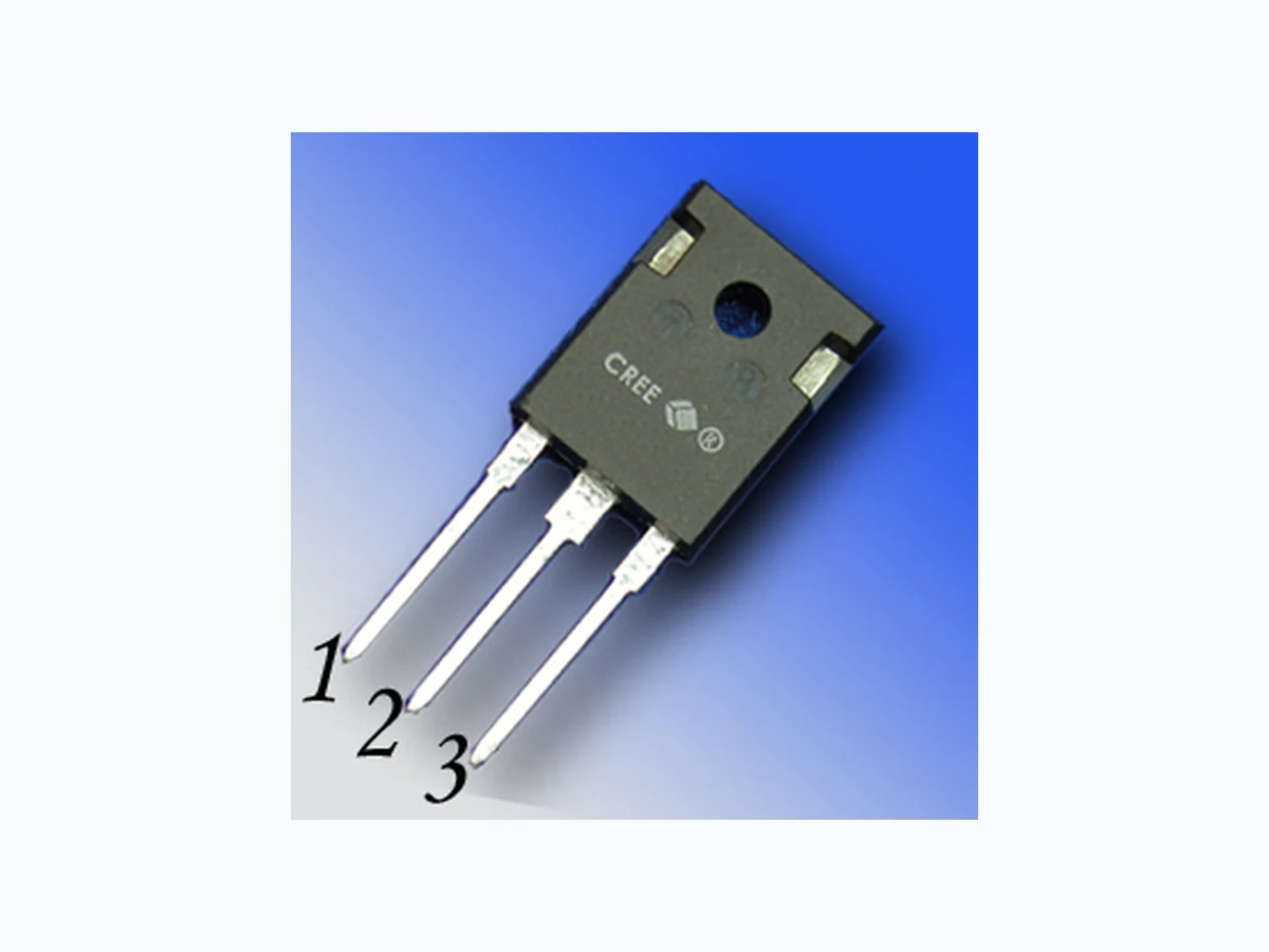
Switch Mode Power Supplies Power Factor Correction Motor Drives Package TO-247-3 Maximum Ratings Symbol Parameter Value Unit Test Conditions Note VRRM Repetitive Peak Reverse Voltage 1200 V VRSM Surge Peak Reverse Voltage 1200 V VDC DC Blocking Voltage 1200 V IF(AVG) Average Forward Current (Per Leg/Device) 10/20 22/44 A TC=160˚C TC=125˚C IF(PEAK) Peak Forward Current (Per Leg/Device) 25/50 A TC=125˚C, TREP<1 mS, Duty=0.5 IFRM Repetitive Peak Forward Surge Current 50* A TC=25˚C, tP=8.3 ms, Half Sine Wave IFSM Non-Repetitive Peak Forward Surge Current 250* A TC=25˚C, tP=10 µs, Pulse Ptot Power Dissipation (Per Leg) 312* 104* W TC=25˚C TC=125˚C TJ , Tstg Operating Junction and Storage Temperature -55 to +175 ˚C ** Per Device, * Per Leg Part Number Package Marking C2D20120D TO-247-3 C2D20120
3.0 V IF = 10 A TJ=25°C
This is a majority carrier diode, so there is no reverse recovery charge. Figure 1. Forward Characteristics Figure 2. Reverse Characteristics
C2D20120 Rev. - Package Dimensions Package TO-247-3 POS Inches Millimeters Min Max Min Max A .605 .631 15.367 16.027 B .800 .830 20.320 21.082 C .620 .799 15.748 20.295 D .095 .126 2.413 3.200 E .046 .052 1.168 1.321 F .060 .084 1.524 2.134 G .215 TYP .215 TYP H .180 .203 4.572 5.156 J .078 .081 1.982 2.057 K 6˚ 21˚ 6˚ 21˚ L 4˚ 6˚ 4˚ 6˚ M 2˚ 4˚ 2˚ 4˚ N 2˚ 4˚ 2˚ 4˚ P .090 .097 2.286 2.464 Q .020 .030 .508 .762 R 9˚ 11˚ 9˚ 11˚ S 9˚ 11˚ 9˚ 11˚ T 2˚ 8˚ 2˚ 8˚ U 2˚ 8˚ 2˚ 8˚ V .138 .144 3.505 3.658
C2D20120 Rev. - This product has not been designed or tested for use in, and is not intended for use in, applications implanted into the human body nor in applications in which failure of the product could lead to death, personal injury or property damage, including but not limited to equipment used in the operation of nuclear facilities, life-support machines, cardiac defibrillators or similar emergency medical equipment, aircraft navigation or communication or control systems, air traffic control systems, or weapons systems. Copyright © 2006 Cree, Inc. All rights reserved. The information in this document is subject to change without notice. Cree, the Cree logo, and Zero Recovery are registered trademarks of Cree, Inc. Cree, Inc.
4600 Silicon Drive
Durham, NC 27703 USA Tel: +1.919.313.5300 Fax: +1.919.313.5451 www.cree.com/power Recommended Solder Pad Layout TO-247-3 Part Number Package Marking C2D20120D TO-247-3 C2D20120