

 Download PDF
C2955 HAMAMATSU
Document overview
- PDF pages: 2
Technical content
Page 1
INFRARED IC INTERNAL
INSPECTION SYSTEM
TENTATIVE DATA SHEET
C2955
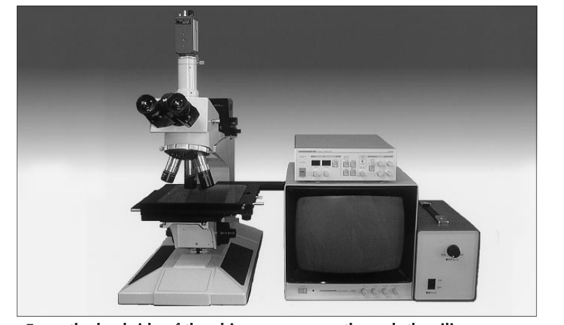
From the backside of the chip, you can see through the silicon
substrate to the patterns of the chip by means of an infrared light.
A newly developed infrared CCD camera is used to inspect pattern
images more clearly and easily than ever before.
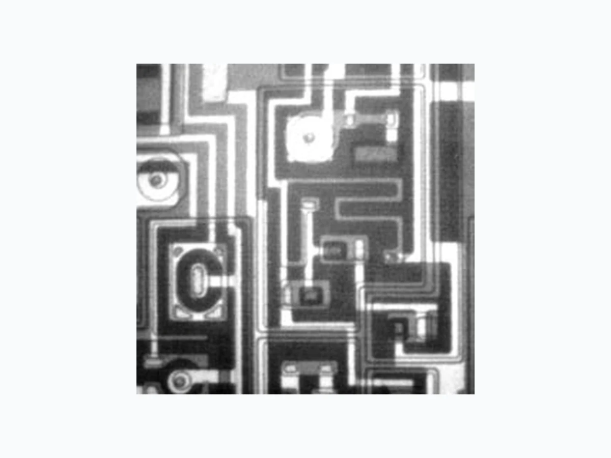
The C2955 is an IC internal inspection system incorporating an infrared microscope and an infrared CCD camera. Use of a newly developed infrared CCD camera enables a high sensitivity approximately ten times that of conventional systems (in comparisons by HAMAMATSU), at a wavelength of 1.0 µm, making it possible to obtain sharp, clear images with high resolution. Using an infrared light which is transmitted through the silicon substrate enables observation of the interconnect lines in the IC, the wire bonding status, and the die bonding conditions, along with the diffusion zone conditions, without damaging the part under observation. Observation can be done from the
back side, when the sample is prepared by scraping away the molding on the side opposite the surface of the silicon substrate. Because the metal wiring is never touched in the inspection process, precise testing can be carried out under optimum conditions, making it possible to inspect the condition of the diffusion zones, the multilayer interconnect lines, the Al-Si nodules wire bonding interfaces, and die bonding details.
G Best suited for flip-chip
evaluation
G No damage to part under
observation
G High sensitivity, high
resolution
G Built-in contrast
enhancement function
G Shading correction function
Page 2
SPECIFICATIONS
G Infrared CCD Camera (camera head, camera control unit) Imaging device ..............................................2/3-inch infrared CCD Spectral response .........................................400 nm to 1200 nm No. of pixels ..................................................380,000 Effective photocathode size ......................... 6.3 × 4.7 mm Power consumption ..................................... 20 VA G Video Monitor CRT............................................................... 12-inch/Black and white, high-resolution model Resolution (horizontal center) ...................... 900 TV lines min. Power consumption ..................................... 38 VA
G Infrared Microscope Optical path switching .................................. 100 : 0 / 0 : 100 (eyepiece/camera) Stage travel area ..........................................153 × 153 mm Epi-illuminated light source .......................... 12 V, 100 W halogen lamp Revolver ........................................................5 holes Infrared objectives ........................................10 ×, 20 ×, 50 × (optional: 5 ×, 100 × 1) G Environmental Conditions Ambient operating temperature range ......... 0 to +40°C Ambient storage temperature range ............ -10 to +50°C Ambient operating/storage humidity ............ 90% max. (with no condensation)
Line voltage...................................................100 VAC ± 10%, 50/60 Hz
OPTIONS
COMPONENTS
- C7103 IC Backside Polishing System
- Infrared CCD camera
- Camera control unit
- Video monitor
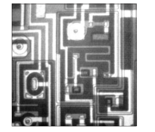
IMAGE EXAMPLE
- Infrared microscope (including light source
dimmer transformer\*)
- Cables: 1 set \* Specify the line voltage at ordering.
APPLICATIONS
- Inspection of flip-chip and other packaged IC devices
- Testing for abnormalities (defects, failures) in metal and polysilicon wiring
- Observation of wire bonding
- Observation of various types of die bonding zones
- Simultaneous inspection of Al-Si nodules and multiple patterns
- Observation of pattern diffusion into substrate
- Identification of ESD failure locations
- Subject to local technical requirements and regulations, availability of products included in this promotional material may vary. Please consult with our sales office.
- Information furnished by HAMAMATSU is believed to be reliable. However, no responsibility is assumed for possible inaccuracies
ISO 9001/ISO 13485
EN 46001
or omissions. Specifications and external appearance are subject to change without notice.
Certificate: 09 105 79045
© 1999 Hamamatsu Photonics K.K.
Homepage Address http://www.hamamatsu.com
HAMAMATSU PHOTONICS K.K., Systems Division 812 Joko-cho, Hamamatsu City, 431-3196, Japan, Telephone: (81)53-431-0124, Fax: (81)53-435-1574, E-mail:export@sys.hpk.co.jp U.S.A. and Canada: Hamamatsu Photonic Systems: 360 Foothill Road, Bridgewater, N.J. 08807-0910, U.S.A., Telephone: (1)908-231-1116, Fax: (1)908-231-0852 Germany: Hamamatsu Photonics Deutschland GmbH: Arzbergerstr. 10, D-82211 Herrsching am Ammersee, Germany, Telephone: (49)8152-375-0, Fax: (49)8152-2658 France: Hamamatsu Photonics France S.A.R.L.: 8, Rue du Saule Trapu, Parc du Moulin de Massy, 91882 Massy Cedex, France, Telephone: (33)1 69 53 71 00, Fax: (33)1 69 53 71 10 United Kingdom: Hamamatsu Photonics UK Limited: Lough Point, 2 Gladbeck Way, Windmill Hill, Enfield, Middlesex EN2 7JA, United Kingdom, Telephone: (44)208-367-3560, Fax: (44)208-367-6384
North Europe: Hamamatsu Photonics Norden AB: Smidesvägen 12, SE-171-41 Solna, Sweden, Telephone: (46)8-509-031-00, Fax: (46)8-509-031-01
Cat. No. SSIS 1025E02
Italy: Hamamatsu Photonics Italia S.R.L.: Strada della Moia, 1/E 20020 Arese (Milano), Italy, Telephone: (39)02-935 81 733, Fax: (39)02-935 81 741
JUL/99 CR Created in Japan (PDF)