


 Download PDF
BZV55-C75 PHILIPS
Document overview
- PDF pages: 13
Technical content
Page 1
1. Product profile
1.1 General description
Low-power voltage regulator diodes in small hermetically sealed glass SOD80C Surface-Mounted Device (SMD) packages. The diodes are available in the normalized E24 2 % (BZV55-B) and approximately 5 % (BZV55-C) tolerance range. The series consists of 37 types with nominal working voltages from 2.4 V to 75 V.
1.2 Features and benefits
Non-repetitive peak reverse power dissipation: 40 W Total power dissipation: 500 mW Two tolerance series: 2 % and 5 %
1.3 Applications
General regulation functions
1.4 Quick reference data
Table 1. Quick reference data Symbol Parameter forward voltage
IF = 10 mA
VF non-repetitive peak PZSM reverse power dissipation
[1] tp = 100 s; square wave; Tj = 25 C prior to surge
2. Pinning information
Table 2. Pinning Pin
Description
1
cathode
2
anode
[1] The marking band indicates the cathode.
Wide working voltage range: nominal 2.4 V to 75 V (E24 range) Low differential resistance Small hermetically sealed glass SMD package
Conditions
Min Typ Max Unit
- - 0.9 V
[1] - - 40 W
Simplified outline Graphic symbol [1]
k
a
2 1
006aaa152

Page 2
3. Ordering information
Table 3. Ordering information
| Type number | Package | ||
|---|---|---|---|
| Name | Description | Version |
- hermetically sealed glass surface-mounted
SOD80C
BZV55-B2V4 to BZV55-C75[1]
package; 2 connectors
[1] The series consists of 74 types with nominal working voltages from 2.4 V to 75 V.
4. Marking
Table 4. Marking codes Type number
Marking code
BZV55-B2V4 to BZV55-C75
marking band
5. Limiting values
Table 5. Limiting values In accordance with the Absolute Maximum Rating System (IEC 60134). Symbol Parameter
Conditions
Min Max Unit
forward current
- 250 mA
IF
[1] -
non-repetitive peak
see
IZSM reverse current
Table 8 and 9
[1] -
PZSM non-repetitive peak
40 W
reverse power dissipation
[2] -
total power dissipation
Tamb 50 C
400 mW
Ptot
[2] -
Ttp 50 C
500 mW
storage temperature
65 +200 C
Tstg junction temperature
65 +200 C
Tj
[1] tp = 100 s; square wave; Tj = 25 C prior to surge [2] Device mounted on a ceramic substrate of 10 10 0.6 mm.
6. Thermal characteristics
Table 6. Thermal characteristics Symbol Parameter
Conditions
Min Typ Max Unit [1] -
thermal resistance from
in free air
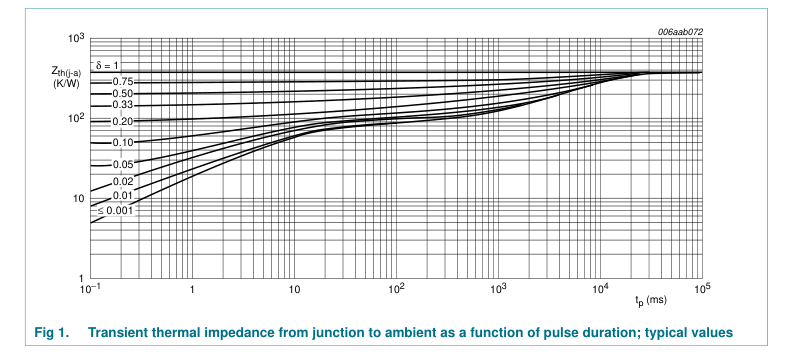
- 380 K/W
Rth(j-a) junction to ambient Rth(j-sp) thermal resistance from
- - 300 K/W
junction to solder point
[1] Device mounted on a ceramic substrate of 10 10 0.6 mm.
2 of 13
Page 3
7. Characteristics
Table 7. Characteristics Tj = 25 C unless otherwise specified. Symbol Parameter forward voltage VF reverse current IR
BZV55-B/C2V4 BZV55-B/C2V7 BZV55-B/C3V0 BZV55-B/C3V3 BZV55-B/C3V6 BZV55-B/C3V9 BZV55-B/C4V3 BZV55-B/C4V7 BZV55-B/C5V1 BZV55-B/C5V6 BZV55-B/C6V2 BZV55-B/C6V8 BZV55-B/C7V5 BZV55-B/C8V2 BZV55-B/C9V1 BZV55-B/C10 BZV55-B/C11 BZV55-B/C12 BZV55-B/C13 BZV55-B/C15 to BZV55-B/C75
Conditions
Min Typ Max Unit
IF = 10 mA
- - 0.9 V
VR = 1 V
- - 50 A
VR = 1 V
- - 20 A
VR = 1 V
- - 10 A
VR = 1 V
- - 5 A
VR = 1 V
- - 5 A
VR = 1 V
- - 3 A
VR = 1 V
- - 3 A
VR = 2 V
- - 3 A
VR = 2 V
- - 2 A
VR = 2 V
- - 1 A
VR = 4 V
- - 3 A
VR = 4 V
- - 2 A
VR = 5 V
- - 1 A
VR = 5 V
- - 700 nA
VR = 6 V
- - 500 nA
VR = 7 V
- - 200 nA
VR = 8 V
- - 100 nA
VR = 8 V
- - 100 nA
VR = 8 V
- - 100 nA
VR = 0.7VZ(nom)
- -
nA
3 of 13
Page 4
Table 8. Characteristics per type; BZV55-B2V4 to BZV55-C24 Tj = 25 C unless otherwise specified.
| Column 1 | Column 2 | Column 3 | Column 4 | Column 5 | Column 6 | Column 7 | Column 8 | Column 9 | Column 10 | Column 11 | Column 12 | Column 13 |
|---|---|---|---|---|---|---|---|---|---|---|---|---|
| BZV55- xxx | Sel | Working voltage V (V) Z | Differential resistance r () dif | Temperature coefficient S (mV/K) Z | Diode capacitance C (pF)[1] d | Non-repetitive peak reverse current I (A)[2] ZSM | ||||||
| I = 5 mA Z | I = 1 mA Z | I = 5 mA Z | I = 5 mA Z | |||||||||
| Min | Max | Typ | Max | Typ | Max | Min | Typ | Max | Max | Max |
2V4 B 2.35 2.45 275 600 70 C 2.2 2.6
2V7 B 2.65 2.75 300 600 75 C 2.5 2.9
3V0 B 2.94 3.06 325 600 80 C 2.8 3.2
3V3 B 3.23 3.37 350 600 85 C 3.1 3.5
3V6 B 3.53 3.67 375 600 85 C 3.4 3.8
3V9 B 3.82 3.98 400 600 85 C 3.7 4.1
4V3 B 4.21 4.39 410 600 80 C 4.0 4.6
4V7 B 4.61 4.79 425 500 50 C 4.4 5.0
5V1 B 5.0 5.2 400 480 40
C 4.8 5.4
5V6 B 5.49 5.71 80
400 15
C 5.2 6.0
6V2 B 6.08 6.32 40
150 6
C 5.8 6.6
6V8 B 6.66 6.94 30
80 6
C 6.4 7.2
7V5 B 7.35 7.65 30
80 6
C 7.0 7.9
8V2 B 8.04 8.36 40
80 6
C 7.7 8.7
9V1 B 8.92 9.28 40
100 6
C 8.5 9.6
10 B 9.8 10.2 50
150 8
C 9.4 10.6
11 B 10.8 11.2
50 150 10
C 10.4 11.6
12 B 11.8 12.2 50
150 10
C 11.4 12.7
100 3.5 1.6 0
450
6.0
100 3.5 2.0 0
450
6.0
95 3.5 2.1 0
450
6.0
95 3.5 2.4 0
450
6.0
90 3.5 2.4 0
450
6.0
90 3.5 2.5 0
450
6.0
90 3.5 2.5 0
450
6.0
80 3.5 1.4 0.2
300
6.0
60 2.7 0.8 1.2
300
6.0
40 2.0 1.2
2.5 300
6.0
10 0.4 2.3 3.7 200
6.0
15 1.2 3.0 4.5 200
6.0
15 2.5 4.0 5.3 150
4.0
15 3.2 4.6 6.2 150
4.0
15 3.8 5.5 7.0 150
3.0
20 4.5 6.4 8.0 90
3.0
20 5.4 7.4 9.0 85
2.5
25 6.0 8.4 10.0 85
2.5
4 of 13
Page 5
Table 8. Characteristics per type; BZV55-B2V4 to BZV55-C24 …continued Tj = 25 C unless otherwise specified.
| Column 1 | Column 2 | Column 3 | Column 4 | Column 5 | Column 6 | Column 7 | Column 8 | Column 9 | Column 10 | Column 11 | Column 12 | Column 13 |
|---|---|---|---|---|---|---|---|---|---|---|---|---|
| BZV55- xxx | Sel | Working voltage V (V) Z | Differential resistance r () dif | Temperature coefficient S (mV/K) Z | Diode capacitance C (pF)[1] d | Non-repetitive peak reverse current I (A)[2] ZSM | ||||||
| I = 5 mA Z | I = 1 mA Z | I = 5 mA Z | I = 5 mA Z | |||||||||
| Min | Max | Typ | Max | Typ | Max | Min | Typ | Max | Max | Max |
13 B 12.7 13.3 50
170 10
C 12.4 14.1
15 B 14.7 15.3 50
200 10
C 13.8 15.6
16 B 15.7 16.3 50
200 10
C 15.3 17.1
18 B 17.6 18.4 50
225 10
C 16.8 19.1
20 B 19.6 20.4 60
225 15
C 18.8 21.2
22 B 21.6 22.4 60
250 20
C 20.8 23.3
24 B 23.5 24.5 60
250 25
C 22.8 25.6
[1] f = 1 MHz; VR = 0 V [2] tp = 100 s; square wave; Tj = 25 C prior to surge
30 7.0 9.4 11.0 80
2.5
30 9.2 11.4 13.0 75
2.0
40 10.4 12.4 14.0 75
1.5
45 12.4 14.4 16.0 70
1.5
55 12.3 15.6 18.0 60
1.5
55 14.1 17.6 20.0 60
1.25
70 15.9 19.6 22.0 55
1.25
5 of 13
Page 6
Table 9. Characteristics per type; BZV55-B27 to BZV55-C75 Tj = 25 C unless otherwise specified.
| Column 1 | Column 2 | Column 3 | Column 4 | Column 5 | Column 6 | Column 7 | Column 8 | Column 9 | Column 10 | Column 11 | Column 12 | Column 13 |
|---|---|---|---|---|---|---|---|---|---|---|---|---|
| BZV55- xxx | Sel | Working voltage V (V) Z | Differential resistance r () dif | Temperature coefficient S (mV/K) Z | Diode capacitance C (pF)[1] d | Non-repetitive peak reverse current I (A)[2] ZSM | ||||||
| I = 2 mA Z | I = 0.5 mA Z | I = 2 mA Z | I = 2 mA Z | |||||||||
| Min | Max | Typ | Max | Typ | Max | Min | Typ | Max | Max | Max |
27 B 26.5 27.5 65
300 25
C 25.1 28.9
30 B 29.4 30.6 70
300 30
C 28.0 32.0
33 B 32.3 33.7 75
325 35
C 31.0 35.0
36 B 35.3 36.7 80
350 35
C 34.0 38.0
39 B 38.2 39.8 80
350 40
C 37.0 41.0
43 B 42.1 43.9 85
375 45
C 40.0 46.0
47 B 46.1 47.9 85
375 50
C 44.0 50.0
51 B 50.0 52.0 90
400 60
C 48.0 54.0
56 B 54.9 57.1 100 425 70 C 52.0 60.0
62 B 60.8 63.2 120 450 80 C 58.0 66.0
68 B 66.6 69.4 150 475 90 C 64.0 72.0
75 B 73.5 76.5 170 500 95 C 70.0 79.0
[1] f = 1 MHz; VR = 0 V [2] tp = 100 s; square wave; Tj = 25 C prior to surge
80 18.0 22.7 25.3 50
1.0
80 20.6 25.7 29.4 50
1.0
80 23.3 28.7 33.4 45
0.9
90 26.0 31.8 37.4 45
0.8
130 28.7 34.8 41.2 45
0.7
150 31.4 38.8 46.6 40
0.6
170 35.0 42.9 51.8 40
0.5
180 38.6 46.9 57.2 40
0.4
200 42.2 52.0 63.8 40
0.3
215 58.8 64.4 71.6 35
0.3
240 65.6 71.7 79.8 35
0.25
255 73.4 80.2 88.6 35
0.2
6 of 13
Page 7
| 103 mbg801 PZSM (W) 102 (1) 10 (2) 1 10−1 1 10 tp (ms) (1) Tj = 25 C (prior to surge) (2) Tj = 150 C (prior to surge) Fig 2. Non-repetitive peak reverse power dissipation as a function of pulse duration; maximum values | mbg781 300 IF (mA) 200 100 0 0.6 0.8 1 VF (V) Tj = 25 C Fig 3. Forward current as a function of forward voltage; typical values |
|---|---|
| mbg783 0 SZ (mV/K) 4V3 −1 3V9 3V6 −2 3V3 3V0 2V4 2V7 −3 0 20 40 IZ (mA) 60 BZV55-B/C2V4 to BZV55-B/C4V3 Tj = 25 C to 150 C Fig 4. Temperature coefficient as a function of working current; typical values | mbg782 10 12 SZ 11 (mV/K) 10 9V1 5 8V2 7V5 6V8 6V2 5V6 5V1 0 4V7 −5 0 4 8 12 16 20 IZ (mA) BZV55-B/C4V7 to BZV55-B/C12 Tj = 25 C to 150 C Fig 5. Temperature coefficient as a function of working current; typical values |
7 of 13
Page 8
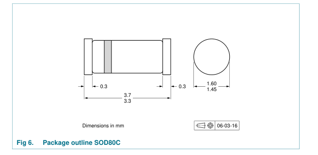
8. Package outline
9. Packing information
Table 10. Packing methods The indicated -xxx are the last three digits of the 12NC ordering code.[1]
| Type number Package Description | Packing quantity | |
|---|---|---|
| 2500 | 10000 |
BZV55-B2V4 to SOD80C 4 mm pitch, 8 mm tape and reel
-115 -135
BZV55-C75
[1] For further information and the availability of packing methods, see Section 13.
8 of 13
Page 9
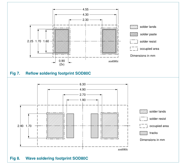
10. Soldering
9 of 13
Page 10
11. Revision history
Table 11. Revision history Document ID
Release date
Data sheet status
Change notice
Supersedes
BZV55_SER v.5
20110126
-
BZV55_SER v.4
- Section 4 “Marking”: updated
Modifications:
- Table 6 “Thermal characteristics”: changed Rth(j-t) for Rth(j-sp)
- Figure 6: superseded by minimized outline drawing
- Section 12 “Legal information”: updated
BZV55_SER v.4
20070719
CPCN200508022F
BZV55 v.3
BZV55 v.3
20020228
Product specification
-
BZV55 v.2
BZV55 v.2
19990521
Product specification
-
BZV55 v.1
BZV55 v.1
19960426
Product specification
-
-
10 of 13
Page 11
12. Legal information
12.1 Data sheet status
Document status[1][2]
Product status[3]
Definition This document contains data from the objective specification for product development.
Objective [short] data sheet
Development
This document contains data from the preliminary specification.
Preliminary [short] data sheet Qualification
This document contains the product specification.
Product [short] data sheet
Production
[1] Please consult the most recently issued document before initiating or completing a design. [2] The term ‘short data sheet’ is explained in section “Definitions”. [3] The product status of device(s) described in this document may have changed since this document was published and may differ in case of multiple devices. The latest product status information is available on the Internet at URL http://www.nxp.com.
12.2 Definitions
Draft — The document is a draft version only. The content is still under internal review and subject to formal approval, which may result in modifications or additions. NXP Semiconductors does not give any representations or warranties as to the accuracy or completeness of information included herein and shall have no liability for the consequences of use of such information. Short data sheet — A short data sheet is an extract from a full data sheet with the same product type number(s) and title. A short data sheet is intended for quick reference only and should not be relied upon to contain detailed and full information. For detailed and full information see the relevant full data
sheet, which is available on request via the local NXP Semiconductors sales office. In case of any inconsistency or conflict with the short data sheet, the full data sheet shall prevail. Product specification — The information and data provided in a Product data sheet shall define the specification of the product as agreed between NXP Semiconductors and its customer, unless NXP Semiconductors and customer have explicitly agreed otherwise in writing. In no event however, shall an agreement be valid in which the NXP Semiconductors product is deemed to offer functions and qualities beyond those described in the Product data sheet.
12.3 Disclaimers
Limited warranty and liability — Information in this document is believed to be accurate and reliable. However, NXP Semiconductors does not give any representations or warranties, expressed or implied, as to the accuracy or completeness of such information and shall have no liability for the consequences of use of such information. In no event shall NXP Semiconductors be liable for any indirect, incidental, punitive, special or consequential damages (including - without limitation - lost profits, lost savings, business interruption, costs related to the removal or replacement of any products or rework charges) whether or not such damages are based on tort (including negligence), warranty, breach of
contract or any other legal theory. Notwithstanding any damages that customer might incur for any reason whatsoever, NXP Semiconductors’ aggregate and cumulative liability towards customer for the products described herein shall be limited in accordance with the Terms and conditions of commercial sale of NXP Semiconductors. Right to make changes — NXP Semiconductors reserves the right to make changes to information published in this document, including without limitation specifications and product descriptions, at any time and without notice. This document supersedes and replaces all information supplied prior to the publication hereof. Suitability for use — NXP Semiconductors products are not designed,
authorized or warranted to be suitable for use in life support, life-critical or safety-critical systems or equipment, nor in applications where failure or
malfunction of an NXP Semiconductors product can reasonably be expected to result in personal injury, death or severe property or environmental damage. NXP Semiconductors accepts no liability for inclusion and/or use of NXP Semiconductors products in such equipment or applications and therefore such inclusion and/or use is at the customer’s own risk. Applications — Applications that are described herein for any of these products are for illustrative purposes only. NXP Semiconductors makes no representation or warranty that such applications will be suitable for the specified use without further testing or modification. Customers are responsible for the design and operation of their applications
and products using NXP Semiconductors products, and NXP Semiconductors accepts no liability for any assistance with applications or customer product design. It is customer’s sole responsibility to determine whether the NXP Semiconductors product is suitable and fit for the customer’s applications and products planned, as well as for the planned application and use of customer’s third party customer(s). Customers should provide appropriate design and operating safeguards to minimize the risks associated with their applications and products. NXP Semiconductors does not accept any liability related to any default, damage, costs or problem which is based on any weakness or default in the
customer’s applications or products, or the application or use by customer’s third party customer(s). Customer is responsible for doing all necessary testing for the customer’s applications and products using NXP Semiconductors products in order to avoid a default of the applications and the products or of the application or use by customer’s third party customer(s). NXP does not accept any liability in this respect. Limiting values — Stress above one or more limiting values (as defined in the Absolute Maximum Ratings System of IEC 60134) will cause permanent damage to the device. Limiting values are stress ratings only and (proper) operation of the device at these or any other conditions above those given in
the Recommended operating conditions section (if present) or the Characteristics sections of this document is not warranted. Constant or repeated exposure to limiting values will permanently and irreversibly affect the quality and reliability of the device. Terms and conditions of commercial sale — NXP Semiconductors products are sold subject to the general terms and conditions of commercial sale, as published at http://www.nxp.com/profile/terms, unless otherwise agreed in a valid written individual agreement. In case an individual agreement is concluded only the terms and conditions of the respective agreement shall apply. NXP Semiconductors hereby expressly objects to
applying the customer’s general terms and conditions with regard to the purchase of NXP Semiconductors products by customer. No offer to sell or license — Nothing in this document may be interpreted or construed as an offer to sell products that is open for acceptance or the grant, conveyance or implication of any license under any copyrights, patents or other industrial or intellectual property rights. Export control — This document as well as the item(s) described herein may be subject to export control regulations. Export might require a prior authorization from national authorities.
11 of 13
Page 12
Quick reference data — The Quick reference data is an extract of the product data given in the Limiting values and Characteristics sections of this document, and as such is not complete, exhaustive or legally binding. Non-automotive qualified products — Unless this data sheet expressly states that this specific NXP Semiconductors product is automotive qualified, the product is not suitable for automotive use. It is neither qualified nor tested in accordance with automotive testing or application requirements. NXP Semiconductors accepts no liability for inclusion and/or use of non-automotive qualified products in automotive equipment or applications. In the event that customer uses the product for design-in and use in
automotive applications to automotive specifications and standards, customer (a) shall use the product without NXP Semiconductors’ warranty of the
13. Contact information
For more information, please visit: http://www.nxp.com
product for such automotive applications, use and specifications, and (b) whenever customer uses the product for automotive applications beyond NXP Semiconductors’ specifications such use shall be solely at customer’s own risk, and (c) customer fully indemnifies NXP Semiconductors for any liability, damages or failed product claims resulting from customer design and use of the product for automotive applications beyond NXP Semiconductors’ standard warranty and NXP Semiconductors’ product specifications.
12.4 Trademarks
Notice: All referenced brands, product names, service names and trademarks are the property of their respective owners.
For sales office addresses, please send an email to: salesaddresses@nxp.com
12 of 13
Page 13
14. Contents
1 Product profile . . . . . . . . . . . . . . . . . . . . . . . . . . 1 1.1 General description . . . . . . . . . . . . . . . . . . . . . 1 1.2 Features and benefits. . . . . . . . . . . . . . . . . . . . 1 1.3 Applications . . . . . . . . . . . . . . . . . . . . . . . . . . . 1 1.4 Quick reference data . . . . . . . . . . . . . . . . . . . . 1 2 Pinning information. . . . . . . . . . . . . . . . . . . . . . 1 3 Ordering information. . . . . . . . . . . . . . . . . . . . . 2 4 Marking . . . . . . . . . . . . . . . . . . . . . . . . . . . . . . . . 2 5 Limiting values. . . . . . . . . . . . . . . . . . . . . . . . . . 2 6 Thermal characteristics . . . . . . . . . . . . . . . . . . 2
7 Characteristics. . . . . . . . . . . . . . . . . . . . . . . . . . 3 8 Package outline . . . . . . . . . . . . . . . . . . . . . . . . . 8 9 Packing information . . . . . . . . . . . . . . . . . . . . . 8 10 Soldering . . . . . . . . . . . . . . . . . . . . . . . . . . . . . . 9 11 Revision history. . . . . . . . . . . . . . . . . . . . . . . . 10 12 Legal information. . . . . . . . . . . . . . . . . . . . . . . 11 12.1 Data sheet status . . . . . . . . . . . . . . . . . . . . . . 11 12.2 Definitions. . . . . . . . . . . . . . . . . . . . . . . . . . . . 11 12.3 Disclaimers . . . . . . . . . . . . . . . . . . . . . . . . . . . 11 12.4 Trademarks. . . . . . . . . . . . . . . . . . . . . . . . . . . 12
13 Contact information. . . . . . . . . . . . . . . . . . . . . 12 14 Contents . . . . . . . . . . . . . . . . . . . . . . . . . . . . . . 13
Please be aware that important notices concerning this document and the product(s) described herein, have been included in section ‘Legal information’.
© NXP B.V. 2011.
All rights reserved.
For more information, please visit: http://www.nxp.com For sales office addresses, please send an email to: salesaddresses@nxp.com
Date of release: 26 January 2011 Document identifier: BZV55_SER