
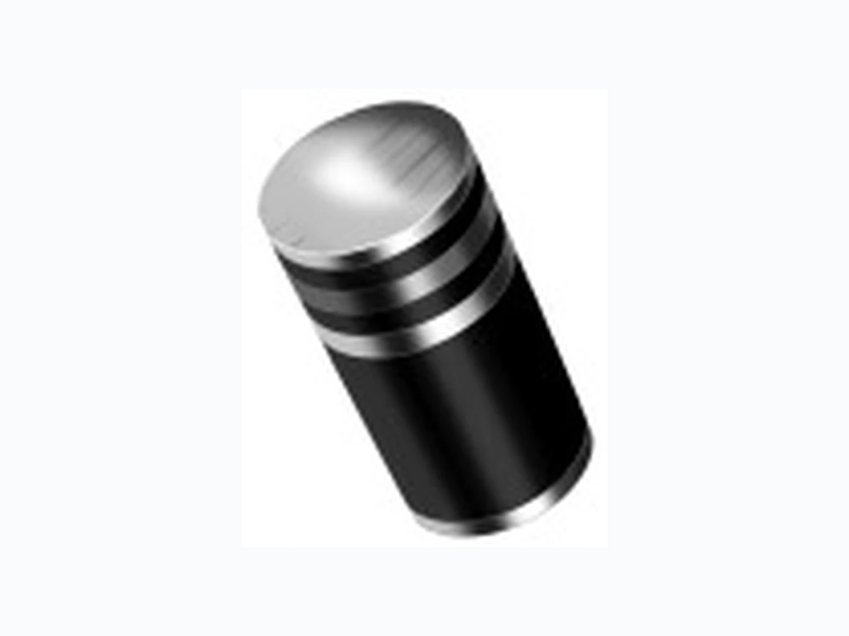
BYM10-50 VISHAY
Document overview
- Manufacturer or author: Provided By www.digicamel.com(free datasheet download site)
- PDF pages: 5
Technical content
BYM10-50 thru BYM10-1000, GL41A thru GL41Y Vishay General Semiconductor Document Number: 88546 Revision: 07-Apr-08 For technical questions within your region, please contact one of the following: PDD-Americas@vishay.com , PDD-Asia@vishay.com , PDD-Europe@vishay.com www.vishay.com Surface Mount Glass Passivated Junction Rectifier
FEATURES
- Superectifier structur e for high reliability condition Patented glass-plastic encapsulation technique Ideal for automated placement Low forward voltage drop Low leakage current High forward surge capability Meets environmental standard MIL-S-19500 Meets MSL level 1, per J-STD-020, LF maximum peak of 250 °C Solder dip 260 °C, 40 s Component in accordance to RoHS 2002/95/EC and WEEE 2002/96/EC TYPICAL APPLICATIONS For use in general purpose rectification of power supplies, inverters, converters and freewheeling diodes for consumer, automotive and telecommunication. MECHANICAL DATA Case: DO-213AB, molded epoxy over glass body Epoxy meets UL 94V-0 flammability rating Terminals: Matte tin plated leads, solderable per J-STD-002 and JESD22-B102 E3 suffix for consumer grade, meets JESD 201 class 1A whisker test, HE3 suffix for high reliability grade (AEC Q101 qualified), meets JESD 201 class 2 whisker test Polarity: Two bands indicate cathode end - 1st band denotes device type and 2nd band denotes repetitive peak reverse voltage rating PRIMARY CHARACTERISTICS IF(AV) 1.0 A VRRM BYM-50-1000 GL41A-Y
50 V to 1000 V
50 V to 1600 V
IR 10 µA EAS 5 mJ VF 1.1 V, 1.2 V TJ max. 175 °C Patented* DO-213AB *Glass-plastic encapsulation is covered by Patent No. 3,996,602, brazed-lead assembly to Patent No. 3,930,306 MAXIMUM RATINGS (TA = 25 °C unless otherwise noted) PARAMETER SYMBOL BYM 10-50 BYM 10-100 BYM 10-200 BYM 10-400 BYM 10-600 BYM 10-800 BYM 10-1000 UNIT STANDARD RECOVERY DEVICE: 1ST BAND IS WHITE GL41A GL41B GL41D GL41G GL41J GL41K GL41M GL41T GL41Y Polarity color bands (2nd band) Gray Red Orange Y ellow Green Blue Violet White Brown Maximum repetitive peak reverse voltage VRRM 50 100 200 400 600 800 1000 1300 1600 V Maximum RMS voltage V RMS 35 70 140 280 420 560 700 910 1120 V Maximum DC blocking voltage V DC 50 100 200 400 600 800 1000 1300 1600 V Maximum average forward rectified current (Fig. 1) IF(AV) 1.0 A
BYM10-50 thru BYM10-1000, GL41A thru GL41Y Vishay General Semiconductor www.vishay.com For technical questions within your region, please contact one of the following: PDD-Americas@vishay.com , PDD-Asia@vishay.com , PDD-Europe@vishay.com Document Number: 88546 Revision: 07-Apr-082 Notes: (1) Thermal resistance from junction to ambient, 0.24 x 0.24" (6.0 x 6.0 mm) copper pads to each terminal (2) Thermal resistance from junction to terminal, 0.24 x 0.24" (6.0 x 6.0 mm) copper pads to each terminal Peak forward surge current 8.3 ms single half sine-wave superimposed on rated load I FSM 30 A Maximum full load reverse current full cycle average at TA = 75 °C IR(AV) 30 µA Non-repetitive peak reverse avalanche energy at TJ = 25 °C, IAS = 1 A, L = 10 mH EAS 5- µ A Operating junction and storage temperature range TJ, TSTG - 65 to + 175 °C MAXIMUM RATINGS (TA = 25 °C unless otherwise noted) PARAMETER SYMBOL BYM 10-50 BYM 10-100 BYM 10-200 BYM 10-400 BYM 10-600 BYM 10-800 BYM 10-1000 UNIT STANDARD RECOVERY DEVICE: 1ST BAND IS WHITE GL41A GL41B GL41D GL41G GL41J GL41K GL41M GL41T GL41Y ELECTRICAL CHARACTERISTICS (TA = 25 °C unless otherwise noted) PARAMETER TEST CONDITIONS SYMBOL BYM 10-50 BYM 10-100 BYM 10-200 BYM 10-400 BYM 10-600 BYM 10-800 BYM 10-1000 UNIT GL41A GL41B GL41D GL41G GL41J GL41K GL41M GL41T GL41Y Maximum instantaneous forward voltage
1.0 A V
F 1.1 1.2 V Maximum DC reverse current at rated DC blocking voltage T A = 25 °C TA = 125 °C IR 10 50 µA Typical junction capacitance 4.0 V, 1 MHz C J 8.0 pF THERMAL CHARACTERISTICS (TA = 25 °C unless otherwise noted) PARAMETER SYMBOL BYM 10-50 BYM 10-100 BYM 10-200 BYM 10-400 BYM 10-600 BYM 10-800 BYM 10- UNIT GL41A GL41B GL41D GL41G GL41J GL41K GL41M GL41T GL41Y Typical thermal resistance RθJA RθJT 75 (1) 30 (2) °C/W
Document Number: 91000 www.vishay.com Revision: 08-Apr-05 1 Notice Specifications of the products displayed herein are subjec t to change without notice. Vishay Intertechnology, Inc., or anyone on its behalf, assumes no responsibility or liability for any errors or inaccuracies. Information contained herein is intended to provide a product description only. No license, express or implied, by estoppel or otherwise, to any intellectual property rights is granted by this document. Except as provided in Vishay's terms and conditions of sale for such products, Vishay assumes no liability whatsoever, and disclaims any express or implied warranty, relating to sale and/or use of Vishay products including liability or warranties relating to fitness for a particular purpose, merchantability, or infringement of any patent, copyright, or other intellectual property right. The products shown herein are not designed for use in medical, life-saving, or life-sustaining applications. Customers using or selling these products for use in such applications do so at their own risk and agree to fully indemnify Vishay for any damages resulting from such improper use or sale.