
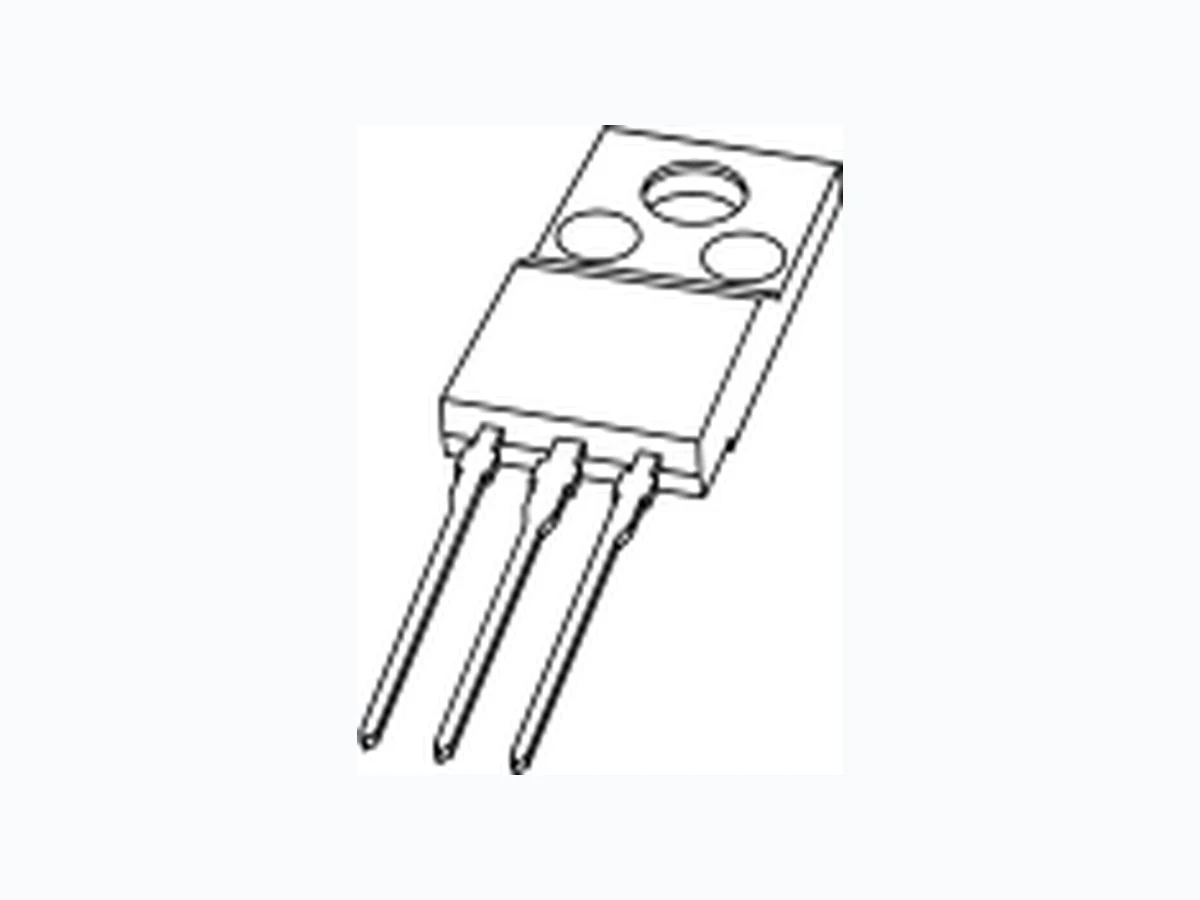
BT236X NXP
Document overview
- Manufacturer or author: Provided By www.digicamel.com(FREE DATASHEET DOWNLOAD SITE)
- PDF pages: 12
Technical content
- Product profile
1.1 General description
Passivated triacs in a full pack, plastic package intended for use in applications requiring high bidirectional transient and blocking voltage capability and thermal cycling performance.
1.2 Features
1.3 Applications
1.4 Quick reference data
- Pinning information BT236X series F and G
6 A Four-quadrant triacs
Rev. 02 — 14 March 2006 Product data sheet ■ Isolated package ■ High ITSM ■ Lamp dimmers ■ High inrush resistive loads ■ Motor speed controllers ■ Heating and static switching ■ VDRM ≤ 600 V (BT236X-600_600F_600G) ■ IGT ≤ 35 mA (BT236X-600_800) ■ VDRM ≤ 800 V (BT236X-800_800G) ■ IGT ≤ 25 mA (BT236X-600F) ■ ITSM ≤ 65 A (t = 20 ms) ■ IGT ≤ 50 mA (BT236X-600G_800G) ■ IT(RMS) ≤ 6A Table 1: Pinning Pin Description Simplified outline Symbol 1 main terminal 1 (T1) SOT186A (3-lead TO-220F) 2 main terminal 2 (T2) 3 gate (G) mb mounting base; isolated 321 mb sym051 G
BT236X_SER_F_G_2 © Koninklijke Philips Electronics N.V. 2006. All rights reserved. Product data sheet Rev. 02 — 14 March 2006 2 of 12 Philips Semiconductors BT236X series F and G
- Ordering information 4. Limiting values [1] Although not recommended, off-state voltages up to 800 V may be applied without damage, but the triac may switch to the on-state. The rate of rise of current should not exceed 6 A/µs. Table 2: Ordering information Type number Package Name Description Version BT236X-600 3-lead TO-220F plastic single-ended package; isolated heatsink mounted; 1 mounting hole; 3 lead TO-220 ‘full pack’ SOT186A BT236X-600F BT236X-600G BT236X-800 BT236X-800G Table 3: Limiting values In accordance with the Absolute Maximum Rating System (IEC 60134). Symbol Parameter Conditions Min Max Unit VDRM repetitive peak off-state voltage BT236X-600 [1] - 600 V BT236X-600F [1] - 600 V BT236X-600G [1] - 600 V BT236X-800 - 800 V BT236X-800G - 800 V I T(RMS) RMS on-state current full sine wave; T h ≤ 88 °C; see Figure4 and5 -6 A ITSM non-repetitive peak on-state current full sine wave; Tj=2 5°C prior to surge; seeFigure2 and3 t = 20 ms - 65 A t = 16.7 ms - 71 A I 2tI 2t for fusing t = 10 ms - 21 A 2s dIT/dt rate of rise of on-state current I TM = 12 A; IG = 0.2 A; dIG /dt = 0.2 A/µs T2+ G+ - 50 A/ µs T2+ G− -5 0 A / µs T2− G− -5 0 A / µs T2− G+ - 10 A/ µs IGM peak gate current - 2 A VGM peak gate voltage - 5 V PGM peak gate power - 5 W PG(AV) average gate power over any 20 ms period - 0.5 W Tstg storage temperature −40 +150 °C Tj junction temperature - 125 °C
BT236X_SER_F_G_2 © Koninklijke Philips Electronics N.V. 2006. All rights reserved. Product data sheet Rev. 02 — 14 March 2006 3 of 12 Philips Semiconductors BT236X series F and G α = conduction angle Fig 1. Total power dissipation as a function of RMS on-state current; maximum values f = 50 Hz Fig 2. Non-repetitive peak on-state current as a function of the number of sinusoidal current cycles; maximum values 003aab307 Th (max) (°C)
0246 IT(RMS) (A)
(W) 107 116 125 a = 180° 120° 90° 60° 30° a a 003aaa968 ITSM n 1 10310210 (A) ITSM t IT Tj = 25 °C max tp
BT236X_SER_F_G_2 © Koninklijke Philips Electronics N.V. 2006. All rights reserved. Product data sheet Rev. 02 — 14 March 2006 4 of 12 Philips Semiconductors BT236X series F and G tp ≤ 20 ms (1) dIT/dt limit (2) T2− G+ quadrant Fig 3. Non-repetitive peak on-state current as a function of pulse duration; maximum values f = 50 Hz; Th ≤ 88 °C Fig 4. RMS on-state current as a function of surge duration; maximum values Fig 5. RMS on-state current as a function of heatsink temperature; maximum values 003aab308 102 103 10-5 10-4 10-3 10-2 10-1 tp ( s) ITSM (A) (1) (2) ITSM t IT Tj(init) = 25 °C max T 003aab309 -2 10-1 1 10 surge duration (s) IT(RMS) (A) 003aab310 -50 0 50 100 150 T h (°C) IT(RMS) (A) 88 °C
BT236X_SER_F_G_2 © Koninklijke Philips Electronics N.V. 2006. All rights reserved. Product data sheet Rev. 02 — 14 March 2006 5 of 12 Philips Semiconductors BT236X series F and G
- Thermal characteristics [1] Full or half cycle with heatsink compound [2] Full or half cycle without heatsink compound 6. Isolation characteristics Table 4: Thermal characteristics Symbol Parameter Conditions Min Typ Max Unit R th(j-h) thermal resistance from junction to heatsink see Figure6 [1] - - 4.5 K/W see Figure6 [2] - - 6.5 K/W R th(j-a) thermal resistance from junction to ambient in free air - 55 - K/W (1) Unidirectional without heatsink compound (2) Unidirectional with heatsink compound (3) Bidirectional without heatsink compound (4) Bidirectional with heatsink compound Fig 6. Transient thermal impedance from junction to heatsink as a function of pulse duration 003aab331 tp (s) 10−5 11 010−110−210−4 10−3 10−1 Zth(j-h) 10−2 (K/W) (1) (2) (3) (4) tp P t Table 5: Isolation limiting values and characteristics Th = 25°C unless otherwise specified. Symbol Parameter Conditions Min Typ Max Unit Visol(rms) RMS isolation voltage from all three terminals to external heatsink; f = 50 Hz to
60 Hz; sinusoidal waveform;
RH ≤ 65 %; clean and dust free - - 2500 V C isol isolation capacitance from pin 2 to external heatsink; f=1M H z -1 0 -p F
BT236X_SER_F_G_2 © Koninklijke Philips Electronics N.V. 2006. All rights reserved. Product data sheet Rev. 02 — 14 March 2006 6 of 12 Philips Semiconductors BT236X series F and G
- Static characteristics Table 6: Static characteristics Tj=2 5°C unless otherwise specified. Symbol Parameter Conditions BT236X-600 BT236X-800 BT236X-600F BT236X-600G BT236X-800G Unit Min Typ Max Min Typ Max Min Typ Max IGT gate trigger current VD =1 2V ; IT = 0.1 A; see Figure8 T2+ G+ - 5 35 - 5 25 - 5 50 mA T2+ G− - 8 35 - 8 25 - 8 50 mA T2− G− - 1 13 5- 1 12 5- 1 15 0m A T2− G+ - 30 70 - 30 70 - 30 100 mA I L latching current VD =1 2V ; IGT = 0.1 A; see Figure10 T2+ G+ - 7 30 - 7 30 - 7 45 mA T2+ G− - 1 64 5- 1 64 5- 1 66 0m A T2− G− - 5 30 - 5 30 - 5 45 mA T2− G+ - 7 45 7 45 - 7 60 mA I H holding current VD =1 2V ; IGT = 0.1 A; see Figure11 - 5 20 - 5 20 - 5 40 mA VT on-state voltage IT =1 0A ; see Figure9 VGT gate trigger voltage VD =1 2V ; IT = 0.1 A; see Figure7 VD = 400 V; IT = 0.1 A; Tj= 125°C ID off-state current VD =V DRM(max); Tj= 125°C
BT236X_SER_F_G_2 © Koninklijke Philips Electronics N.V. 2006. All rights reserved. Product data sheet Rev. 02 — 14 March 2006 7 of 12 Philips Semiconductors BT236X series F and G
- Dynamic characteristics Table 7: Dynamic characteristics Symbol Parameter Conditions BT236X-600 BT236X-800 BT236X-600F BT236X-600G BT236X-800G Unit Min Typ Max Min Typ Max Min Typ Max dVD /dt rate of rise of off-state voltage V DM = 0.67VDRM(max) ; Tj= 125°C; exponentialwaveform; gate open circuit 100 250 - 50 250 - 200 250 - V/ µs dV com /dt rate of change of commutating voltage V DM = 400 V; Tj=9 5°C; IT(RMS) =6A ; dIcom /dt = 3.6 A/ms; gate open circuit; see Figure12 - 20 - - 20 - 10 20 - V/ µs tgt gate- controlled turn-on time I TM =1 2A ; VD =V DRM(max) ; IG = 0.1 A; dIG /dt = 5 A/µs -2 - -2 - - 2 - µs (1) T2− G− (2) T2+G − (3) T2+ G+ (4) T2−G+ Fig 7. Normalized gate trigger voltage as a function of junction temperature Fig 8. Normalized gate trigger current as a function of junction temperature Tj (°C) −50 150 10005 0 001aab101 0.8 1.2 1.6 0.4 VGT VGT(25°C) 001aae042 Tj (°C) -50 150 10005 0 I GT IGT(25°C) (1) (2) (3) (4) (3) (4) (2) (1)
BT236X_SER_F_G_2 © Koninklijke Philips Electronics N.V. 2006. All rights reserved. Product data sheet Rev. 02 — 14 March 2006 8 of 12 Philips Semiconductors BT236X series F and G Vo = 1.26 V R s = 0.0378Ω (1) Tj= 125°C; typical values (2) Tj= 125°C; maximum values (3) Tj=2 5°C; maximum values Fig 9. On-state current as a function of on-state voltage Fig 10. Normalized latching current as a function of junction temperature The triac should commutate when the dV/dt is below the value on the appropriate curve for pre-commutation dI T/dt. (1) Off-state dV/dt limit for BT236X-600G_800G (2) Off-state dV/dt limit for BT236X-600_800 (3) Off-state dV/dt limit for BT236X-600F Fig 11. Normalized holding current as a function of junction temperature Fig 12. Typical commutation dV/dt as a function of junction temperature 003aab311 0123 V T (V) IT (A) (1) (2) (3) Tj (°C) −50 150 10005 0 001aab100 IL IL(25°C) Tj (°C) −50 150 10005 0 001aab099 IH IH(25°C) 001aae043 Tj (°C) 0 150 10050 102 103 dV/dt (V/µs) (2) (1) (3) 7.9 dlcom /dt
BT236X_SER_F_G_2 © Koninklijke Philips Electronics N.V. 2006. All rights reserved. Product data sheet Rev. 02 — 14 March 2006 9 of 12 Philips Semiconductors BT236X series F and G
- Package outline Fig 13. Package outline SOT186A (3-lead TO-220F) REFERENCESOUTLINE VERSION EUROPEAN PROJECTION ISSUE DATE IEC JEDEC JEITA SOT186A 3-lead TO-220F 0 5 10 mm scale Plastic single-ended package; isolated heatsink mounted; 1 mounting hole; 3 lead TO-220 'full pack' SOT186A A Q c K j Notes 1. Terminal dimensions within this zone are uncontrolled. 2. Both recesses are ˘ 2.5 · 0.8 max. depth D D 1 L L2 L1 e b w M 1 23 q E P T UNIT Db1 D 1 e qQPLc L2 (1) max. e1A 5.08 3mm 4.6 4.0 A 1 2.9 2.5 b 0.9 0.7 1.1 0.9 1.4 1.0 0.7 0.4 15.8 15.2 6.5 6.3 E 10.3 9.7 2.54 14.4 13.5 T(2) 2.5 0.4 3.30 2.79 j 2.7 1.7 K 0.6 0.4 2.6 2.3 3.0 2.6 w 3.2 3.0 DIMENSIONS (mm are the original dimensions) 02-04-09 06-02-14 mounting base
BT236X_SER_F_G_2 © Koninklijke Philips Electronics N.V. 2006. All rights reserved. Product data sheet Rev. 02 — 14 March 2006 10 of 12 Philips Semiconductors BT236X series F and G
- Revision history Table 8: Revision history Document ID Release date Data sheet status Change notice Doc. number Supersedes BT236X_SER_F_G_2 20060314 Product data sheet - - - Modifications:
- InFigure7,Figure8,Figure10 andFigure11: spaces have been removed between 25 and degree signs.
- InFigure5: the figure note has been deleted.
- Figure8: has been modified.
- InTable3: corrected the symbol dIT/dt.
- The entry in IMPULSE has been modified by PD Coding (updated to SOT186A for all types). BT236X_SER_F_G_1 20060209 Product data sheet - - -
Philips Semiconductors BT236X series F and G BT236X_SER_F_G_2 © Koninklijke Philips Electronics N.V. 2006. All rights reserved. Product data sheet Rev. 02 — 14 March 2006 11 of 12 11. Data sheet status [1] Please consult the most recently issued data sheet before initiating or completing a design. [2] The product status of the device(s) described in this data sheet may have changed since this data sheet was published. The latest information is available on the Internet at URL http://www.semiconductors.philips.com. [3] For data sheets describing multiple type numbers, the highest-level product status determines the data sheet status. 12. Definitions Short-form specification —The data in a short-form specification is extracted from a full data sheet with the same type number and title. For detailed information see the relevant data sheet or data handbook. Limiting values definition — Limiting values given are in accordance with the Absolute Maximum Rating System (IEC 60134). Stress above one or more of the limiting values may cause permanent damage to the device. These are stress ratings only and operation of the device at these or at any other conditions above those given in the Characteristics sections of the specification is not implied. Exposure to limiting values for extended periods may affect device reliability. Application information — Applications that are described herein for any of these products are for illustrative purposes only. Philips Semiconductors makes no representation or warranty that such applications will be suitable for the specified use without further testing or modification. 13. Disclaimers Life support —These products are not designed for use in life support appliances, devices, or systems where malfunction of these products can reasonably be expected to result in personal injury. Philips Semiconductors customers using or selling these products for use in such applications do so at their own risk and agree to fully indemnify Philips Semiconductors for any damages resulting from such application. Right to make changes —Philips Semiconductors reserves the right to make changes in the products - including circuits, standard cells, and/or software - described or contained herein in order to improve design and/or performance. When the product is in full production (status ‘Production’), relevant changes will be communicated via a Customer Product/Process Change Notification (CPCN). Philips Semiconductors assumes no responsibility or liability for the use of any of these products, conveys no license or title under any patent, copyright, or mask work right to these products, and makes no representations or warranties that these products are free from patent, copyright, or mask work right infringement, unless otherwise specified. 14. Trademarks Notice —All referenced brands, product names, service names and trademarks are the property of their respective owners. 15. Contact information For additional information, please visit: http://www.semiconductors.philips.com For sales office addresses, send an email to: sales.addresses@www.semiconductors.philips.com Level Data sheet status[1] Product status[2][3] Definition I Objective data Development This data sheet contains data from the objective specification for product development. Philips Semiconductors reserves the right to change the specification in any manner without notice. II Preliminary data Qualification This data sheet contains data from the preliminary specification. Supplementary data will be published at a later date. Philips Semiconductors reserves the right to change the specification without notice, in order to improve the design and supply the best possible product. III Product data Production This data sheet contains data from the product specification. Philips Semiconductors reserves the right to make changes at any time in order to improve the design, manufacturing and supply. Relevant changes will be communicated via a Customer Product/Process Change Notification (CPCN).
© Koninklijke Philips Electronics N.V. 2006 All rights are reserved. Reproduction in whole or in part is prohibited without the prior written consent of the copyright owner. The information presented in this document does not form part of any quotation or contract, is believed to be accurate and reliable and may be changed without notice. No liability will be accepted by the publisher for any consequence of its use. Publication thereof does not convey nor imply any license under patent- or other industrial or intellectual property rights. Date of release: 14 March 2006 Document number: BT236X_SER_F_G_2 Published in The Netherlands Philips Semiconductors BT236X series F and G
- Contents