
Microsoft Word - BT151-D
Document overview
- Manufacturer or author: q-ikuko
- PDF pages: 7
Technical content
Description
Triacs is fabricated using separation diffusion processes ,the junction termination areas are passivated with glass. Thanks to highly sensitive triggering levels and reliability,the Triacs series is suitable for domestic lighting ,heating and motor speed controllers. Symbol BT136(F)-600E4Q Triac
Ordering Information
Part No. Package Packing TO-220 50pcs / Tube Mar,2015-REV.00 www.sddydz.com
Applications
Domestic lighting ,heating and motor speed controllers. BT136-600E ABSOLUTE MAXIMUM RATING PARAMETER SYMBOL RATINGS UNIT 600Repetitive Peak Off State Voltage BT136(F)-600E VDRM V RMS On-state Current (Full sine wave; Tmb≤107°C) IT(RMS) 4 A Non-Repetitive Peak. On-State Current (Full sine wave; Tj=25°C prior to surge) t=20ms t=16.7ms ITSM A I2t For Fusing t=10ms I2t 3.1 A2s Rate of Rise of On-state Current ITM=6A;IG=0.2A,dIG/dt=0.2A/µs T2+G+ T2+G- T2-G- T2-G+ dIT /dt A/µs
2 APeak Gate Current IGM
5 WPeak Gate Power PGM
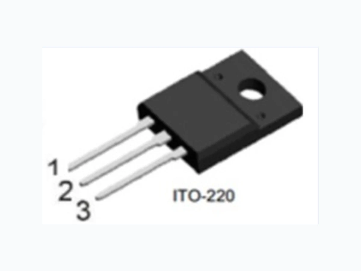
Average Gate Power (Over any 20ms period) PG(AV) 0.5 W Operating Junction Temperature Tj 125 °C Storage Temperature Tstg -40~150 °C ITO-220 50pcs / TubeBT136F-600E
ELECTRICAL CHARACTERISTICS (TJ = 25°C, unless otherwise stated) BT136(F)-600E Mar,2015-REV.00 www.sddydz.com PARAMETER SYMBOL MIN TYP MAX UNIT Thermal Resistance Junction to Mounting Base Full cycle Half cycle Rth j-mb 3
3.7 K/W
Thermal Resistance Junction to Ambient In free air Rth j-a 60 K/W PARAMETER SYMBOL TEST CONDITIONS STATIC CHARACTERISTICS Gate Trigger Current IGT VD=12V, IT=0.1A T2+G+ T2+G- T2-G- T2-G+ 2.5 mA Latching Current IL T2+G+ T2+G- T2-G- T2-G+ 2.5 mA On-State Voltage VT VD=12V, IT=0.1A 0.7Gate Trigger Voltage VGT 0.25VD=400V, IT=0.1A; Tj=125°C 0.4 V Holding Current IH 1.4 Off-state Leakage Current ID MIN TYP MAX UNIT VD=12V, IT=0.1A 2.2 15 mA VD=12V, IT=0.1A; Tj=25°C 1.0 V IT=5A 1.7 V VD=600V, Tj=125°C 0.1 0.5 mA DYNAMIC CHARACTERISTICS Critical Rate of Rise of off-state Voltage dVD/dt VDM=67% VDRM(max), Tj=125°C Exponential waveform,Gate open circuit
50 V/µs
Gate Controlled Turn-on Time tgt ITM=6A,VD=VDRM,IG=0.1A dIG/dt=5A/µs 2 µs 4Q Triac
BT136(F)-600E Mar,2015-REV.00 www.sddydz.com 4Q Triac - 50 1501000 50 IT(RMS) (A) Tmb (°C) Fig. 1. RMS on-state current as a function of mounting base temperature; maximum values IT(RMS) (A) surge duration (s) 10- 2 10110- 1 f = 50 Hz Tmb ≤ 107 °C Fig. 2. RMS on-state current as a function of surge duration; maximum values Ptot (W) IT(RMS) (A) 0 542 31 conduction angle (degrees) form factor a 120 180 2.8 2.2 1.9 1.57 α α = 180° 120° 90° 60° 30° α = conduction angle a = form factor = IT(RMS) / IT(AV) Fig. 3. Total power dissipation as a function of RMS on-state current; maximum values
Mar.2015-REV.00 www.sddydz.com 4Q Triac BT136(F)-600E ITSM (A) number of cycles 1 10410310 102 ITSM t IT Tj(init) = 25 °C max 1/f f = 50 Hz Fig. 4. Non-repetitive peak on-state current as a function of the number of sinusoidal current cycles; maximum values tp (s) 10- 5 10- 110- 210- 4 10- 3 102 103 ITSM (A) ITSM t IT Tj(init) = 25 °C max tp (1) (2) tp ≤ 20 ms (1) dIT/dt limit (2) T2- G+ quadrant limit Fig. 5. Non-repetitive peak on-state current as a function of pulse width; maximum values
4Q Triac BT136(F)-600E 10- 5 1 1010- 110- 210- 4 10- 3 10- 1 Zth(j-mb) (K/W) 10- 2 bidirectional unidirectional tp P t tp (s) Fig. 6. Transient thermal impedance from junction to mounting base as a function of pulse width Tj (°C) - 60 14090- 10 40 (1) (2) (3) (4) (1) (2) (3) (4) IGT IGT (25 °C) (1) T2- G+ (2) T2- G- (3) T2+ G- (4) T2+ G+ Fig. 7. Normalized gate trigger current as a function of junction temperature - 60 14090- 10 40 IL IL(25°C) Tj (°C) Fig. 8. Normalized latching current as a function of junction temperature 5 of 7Mar.2015-REV.00 www.sddydz.com
4Q Triac BT136(F)-600E - 60 14090- 10 40 1.0 0.5 1.5 2.0 IH IH(25°C) Tj (°C) Fig. 9. Normalized holding current as a function of junction temperature VT (V) 0 321 IT (A) (1) (2) (3) Vo = 1.27 V Rs = 0.091 Ω (1) Tj = 125 °C; typical values (2) Tj = 125 °C; maximum values (3) Tj = 25 °C; maximum values Fig. 10. On-state current as a function of on-state voltage - 60 14090- 10 40 0.8 0.4 1.2 1.6 VGT VGT (25 °C) Fig. 11. Normalized gate trigger voltage as a function of junction temperature Tj (°C) 6 of 7Mar.2015-REV.00 www.sddydz.com
Mar.2015-REV.00 www.sddydz.com BT136(F)-600E ITO-220 Mechanical Drawing