

 Download PDF
BS107P
Document overview
- PDF pages: 5
Technical content
Page 1
200V N-CHANNEL ENHANCEMENT MODE VERTICAL DMOSFET
Features
BVDSS > 200V RDS(ON) ≤ 23Ω @ VGS= 2.6V ID = 120mA Maximum Continuous Drain Current Totally Lead-Free & Fully RoHS Compliant (Notes 1 & 2) Halogen and Antimony Free. “Green” Device (Note 3) For automotive applications requiring specific change control (i.e.: parts qualified to AEC-Q101, PPAP capable, and manufactured in IATF 16949 certified facilities), please refer to the related automotive grade (Q-suffix) part. A listing can be found at https://www.diodes.com/products/automotive/automotiveproducts/. This part is qualified to JEDEC standards (as references in AEC-Q101) for High Reliability. https://www.diodes.com/quality/product-definitions/
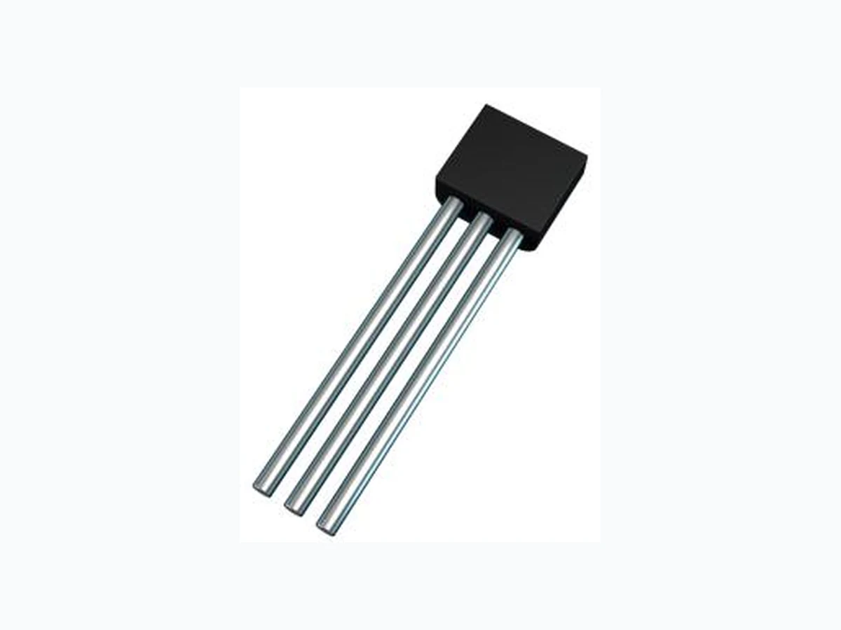
E-Line
(TO-92 Compatible)
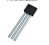
Device Symbol
Flat Face View
Ordering Information (Note 4)
Mechanical Data
Case: E-Line (TO-92 Compatible) Case Material: Molded Plastic, “Green” Molding Compound UL Flammability Rating 94V-0 Terminals: Finish - Matte Tin Plated Leads, Solderable per MIL-STD-202, Method 208 Weight: 0.159 grams (Approximate)
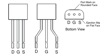
Rounded Face View
| Product | Marking | Package | Leads | Quantity |
| BS107P | BS107 | E-Line | Straight | 4,000 Loose in a Box |
| BS107PSTZ | BS107 | E-Line | Joggled | 2,000 Taped per Ammo Box |
Notes: 1. No purposely added lead. Fully EU Directive 2002/95/EC (RoHS), 2011/65/EU (RoHS 2) & 2015/863/EU (RoHS 3) compliant. 2. See https://www.diodes.com/quality/lead-free/ for more information about Diodes Incorporated’s definitions of Halogen- and Antimony-free, "Green" and Lead-free. 3. Halogen- and Antimony-free "Green” products are defined as those which contain <900ppm bromine, <900ppm chlorine (<1500ppm total Br + Cl) and <1000ppm antimony compounds. 4. For packaging details, go to our website at https://www.diodes.com/design/support/packaging/diodes-packaging/.
Marking Information
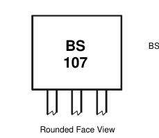
BS107 = Product Type Marking Code
1 of 5
Page 2
Maximum Ratings (@TA = +25°C, unless otherwise specified.)
| Characteristic | Symbol | Value | Unit |
| Drain-Source Voltage | VDSS | 200 | V |
| Gate-Source Voltage | VGSS | ±20 | V |
| Continuous Drain Current | ID | 120 | mA |
| Pulsed Drain Current | IDM | 2 | A |
Thermal Characteristics (@TA = +25°C, unless otherwise specified.)
| Characteristic | Symbol | Value | Unit | |
|---|---|---|---|---|
| Power Dissipation | (Note 5) | PD | 500 | mW |
| Thermal Resistance, Junction to Ambient | (Note 5) | RθJA | 200 | °C/W |
| Thermal Resistance, Junction to Leads | (Note 6) | RθJL | 71 | °C/W |
| Operating and Storage Temperature Range | TJ, TSTG | -55 to +150 | °C | |
Notes: 5. For a through-hole device mounted on the minimum recommended pad layout with 12mm lead length from the bottom of package to the single-sided FR-4 PCB; device is measured under still air conditions whilst operating in a steady-state. 6. Thermal resistance from junction to solder-point at the seating plane (2.5mm from the bottom of package along the drain lead).
Electrical Characteristics (@TA = +25°C, unless otherwise specified.)
| Characteristic | Symbol | Min | Typ | Max | Unit | Test Condition |
| OFF CHARACTERISTICS | ||||||
| Drain-Source Breakdown Voltage | BVDSS | 200 | 230 | | V | ID = 100µA, VGS = 0V |
| Zero Gate Voltage Drain Current | IDSS | | | 30 | nA | VDS = 130V, VGS = 0V |
| Drain Cut-Off Current | IDSX | | | 1 | µA | VDS = 70V, VGS = 0.2V |
| Gate-Source Leakage | IGSS | | | ±10 | nA | VGS = 15V, VDS = 0V |
| ON CHARACTERISTICS | ||||||
| Gate Threshold Voltage | VGS(TH) | 1.0 | | 3.0 | V | ID = 1mA, VDS = VGS |
| Static Drain-Source On-Resistance (Note 7) | RDS(ON) | | 15 | 23 | Ω | VGS = 2.6V, ID = 25mA |
| | 30 | VGS = 5V, ID = 100mA | ||||
| Forward Transconductance (Notes 7 & 9) | gfs | 100 | | | mS | VDS = 25V, ID = 250mA |
| DYNAMIC CHARACTERISTICS (Note 9) | ||||||
| Input Capacitance | Ciss | | | 85 | pF | VDS = 25V, VGS = 0V f = 1.0MHz |
| Output Capacitance | Coss | | | 20 | ||
| Reverse Transfer Capacitance | Crss | | | 7 | ||
| Turn-On Delay Time (Note 8) | tD(ON) | | | 7 | ns | VDD = 25V, ID = 250mA |
| Turn-On Rise Time (Note 8) | tR | | | 8 | ||
| Turn-Off Delay Time (Note 8) | tD(OFF) | | | 16 | ||
| Turn-Off Fall Time (Note 8) | tF | | | 8 | ||
- Measured under pulsed conditions. Pulse width ≤ 300µs. Duty cycle ≤ 2%. Notes: 8. Switching characteristics are independent of operating junction temperature. Switching times are measured with 50Ω source impedance and <5ns rise time on a pulse generator. 9. For design aid only, not subject to production testing.
2 of 5
Page 3
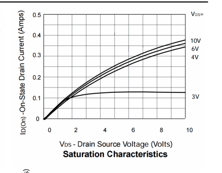
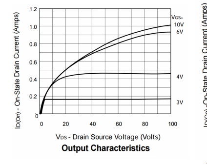
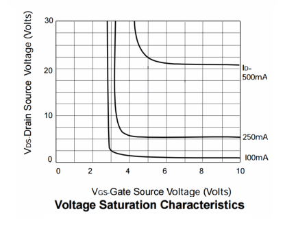
Typical Electrical Characteristics (@TA = +25°C, unless otherwise specified.)
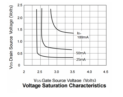
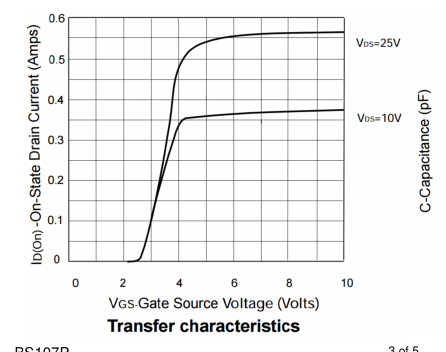
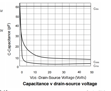
3 of 5
Page 4
Package Outline Dimensions
Please see http://www.diodes.com/package-outlines.html for the latest version.
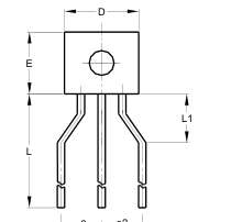
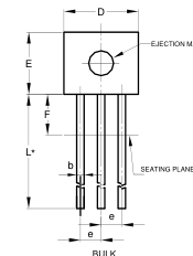
A
| E-Line | |||
| Dim | Min | Max | Typ |
| A | 2.16 | 2.41 | |
| b | 0.41 | 0.495 | |
| b1 | 0.41 | 0.495 | |
| D | 4.37 | 4.77 | |
| E | 3.61 | 4.01 | |
| e | | | 1.27 |
| e2 | | | 2.54 |
| F | | 2.50 | |
| L | 13.00 | 13.97 | |
| L1 | 2.50 | 3.50 | |
| All Dimensions in mm | |||
e2 e2
AMMO
b1
R 1.14 (.045)
4 of 5
Page 5
IMPORTANT NOTICE
DIODES INCORPORATED MAKES NO WARRANTY OF ANY KIND, EXPRESS OR IMPLIED, WITH REGARDS TO THIS DOCUMENT, INCLUDING, BUT NOT LIMITED TO, THE IMPLIED WARRANTIES OF MERCHANTABILITY AND FITNESS FOR A PARTICULAR PURPOSE (AND THEIR EQUIVALENTS UNDER THE LAWS OF ANY JURISDICTION).
Diodes Incorporated and its subsidiaries reserve the right to make modifications, enhancements, improvements, corrections or other changes without further notice to this document and any product described herein. Diodes Incorporated does not assume any liability arising out of the application or use of this document or any product described herein; neither does Diodes Incorporated convey any license under its patent or trademark rights, nor the rights of others. Any Customer or user of this document or products described herein in such applications shall assume all risks of such use and will agree to hold Diodes Incorporated and all the companies whose products are represented on Diodes Incorporated
website, harmless against all damages.
Diodes Incorporated does not warrant or accept any liability whatsoever in respect of any products purchased through unauthorized sales channel. Should Customers purchase or use Diodes Incorporated products for any unintended or unauthorized application, Customers shall indemnify and hold Diodes Incorporated and its representatives harmless against all claims, damages, expenses, and attorney fees arising out of, directly or indirectly, any claim of personal injury or death associated with such unintended or unauthorized application.
Products described herein may be covered by one or more United States, international or foreign patents pending. Product names and markings noted herein may also be covered by one or more United States, international or foreign trademarks.
This document is written in English but may be translated into multiple languages for reference. Only the English version of this document is the final and determinative format released by Diodes Incorporated.
LIFE SUPPORT
Diodes Incorporated products are specifically not authorized for use as critical components in life support devices or systems without the express written approval of the Chief Executive Officer of Diodes Incorporated. As used herein:
A. Life support devices or systems are devices or systems which:
- are intended to implant into the body, or
- support or sustain life and whose failure to perform when properly used in accordance with instructions for use provided in the labeling can be reasonably expected to result in significant injury to the user.
B. A critical component is any component in a life support device or system whose failure to perform can be reasonably expected to cause the failure of the life support device or to affect its safety or effectiveness.
Customers represent that they have all necessary expertise in the safety and regulatory ramifications of their life support devices or systems, and acknowledge and agree that they are solely responsible for all legal, regulatory and safety-related requirements concerning their products and any use of Diodes Incorporated products in such safety-critical, life support devices or systems, notwithstanding any devices- or systems-related information or support that may be provided by Diodes Incorporated. Further, Customers must fully indemnify Diodes Incorporated and its representatives against any damages arising out of the use of Diodes Incorporated products in such safety-critical, life support devices or systems.
Copyright © 2019, Diodes Incorporated
5 of 5