


 Download PDF
BR211SM PHILIPS
Document overview
- PDF pages: 6
Technical content
Page 1
GENERAL DESCRIPTION
QUICK REFERENCE DATA
A range of bidirectional, breakover
SYMBOL PARAMETER
MIN.
MAX. UNIT
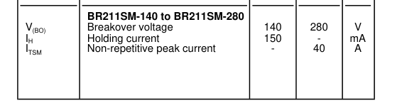
diodes in a two terminal, surface mounting, plastic envelope. These devices feature controlled breakover voltage and high holding current together with high peak current handling
capability.
Typical
application is transient overvoltage protection in telecommunications equipment.
OUTLINE - SOD106
SYMBOL
LIMITING VALUES
Limiting values in accordance with the Absolute Maximum System (IEC 134).
SYMBOL PARAMETER
CONDITIONS
MIN.
MAX. UNIT
VD
Continuous voltage
- 75% of
V
V(BO)typ
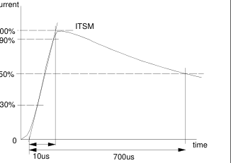
ITSM1
Non repetitive peak current
10/320 µs impulse equivalent to
- 40 A
10/700 µs, 1.6 kV voltage impulse (CCITT K17)
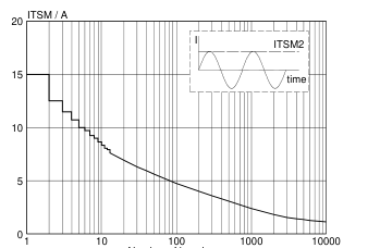
ITSM2
Non repetitive on-state current half sine wave; t = 10 ms;
- 15 A
Tj = 70 ˚C prior to surge
I2t
I2t for fusing
A2s
tp = 10 ms
- 1.1
dIT/dt
Rate of rise of on-state current
tp = 10 µs
- 50 A/µs
after V(BO) turn-on
Ptot
Continuous dissipation
Ta = 25˚C
- 1.2 W
PTM
Peak dissipation
tp = 1 ms; Ta = 25˚C
- 50 W
Tstg
Storage temperature
- 40
150 ˚C
Ta
Operating ambient temperature off-state
- 70 ˚C
Tvj
Overload junction temperature on-state
- 150 ˚C
THERMAL RESISTANCES
SYMBOL PARAMETER
CONDITIONS
MIN. TYP. MAX. UNIT
Rth j-sp
Thermal resistance junction to
- - 12 K/W
solder point
Rth j-a
Thermal resistance junction to pcb mounted; minimum footprint
- 100 - K/W
ambient
Zth j-a
Thermal impedance junction to tp = 1 ms
- 2.62 - K/W
ambient
Page 2
STATIC CHARACTERISTICS
Tj = 25 ˚C unless otherwise stated
SYMBOL PARAMETER
CONDITIONS
1 VTM
On-state voltage
ITM = 2 A
Avalanche voltage (min)
I(BR) = 10mA
V(BR) V(BO)
Breakover voltage (max)
I ≤ IS, tp = 100 µs BR211SM-140 BR211SM-160 BR211SM-180 BR211SM-200 BR211SM-220 BR211SM-240 BR211SM-260 BR211SM-280
Temperature coefficient of V(BR)
S(br) 2 IH
Holding current
Tj = 25˚C Tj = 70˚C
3 IS
Switching current
tp = 100 µs
4 ID
Off-state current
VD = 85% V(BR)min, Tj = 70˚C
DYNAMIC CHARACTERISTICS
Tj = 25 ˚C unless otherwise stated
SYMBOL PARAMETER
CONDITIONS
dVD/dt
Linear rate of rise of off-state
V(DM) = 85% V(BR)min; Tj = 70 ˚C
voltage that will not trigger any device
Cj
Off-state capacitance
VD = 0 V; f = 1 kHz to 1 MHz
VT
MIN. TYP. MAX. UNIT
- - 2.5 V
123 140 157
V
140 160 180
V
158 180 202
V
176 200 224
V
193 220 247
V
211 240 269
V
228 260 292
V
246 280 314
V
- +0.1 - %/K
150 - - mA
100 - - mA
10 200 1000 mA - - 10 µA
MIN. TYP. MAX. UNIT
- - 2000 V/µs
- - 100 pF
current
current
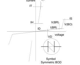
Fig.2. Test waveform for high voltage impulse (ITSM1)
Fig.1. Definition of breakover diode characteristics.
according to CCITT vol IX-Rec K17.
1 Measured under pulsed conditions to avoid excessive dissipation 2 The minimum current at which the diode will remain in the on-state 3 The avalanche current required to switch the diode to the on-state 4 Measured at maximum recommended continuous voltage. Relative humidity < 65%.
Page 3
Number of impulses
Fig.3. Maximum permissible non-repetitive on-state current based on sinusoidal currents; f = 50 Hz; device triggered at the start of each pulse; Tj = 70˚C
prior to surge.
V(BR)(Tj) V(BR)(25 C)
Tj / C
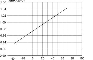
Fig.4. Normalised avalanche breakdown voltage V(BR) and V(BO) as a function of temperature.
IT / A
VT / V
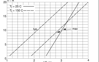
Fig.5. On-state current as a function of on-state voltage; tp = 200 µs to avoid excessive dissipation.
ID / uA
Tj / C
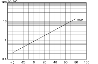
Fig.6. Maximum off-state current as a function of
temperature.
IS / A
Tj / C
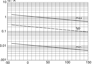
Fig.7. Switching current as a function of junction
temperature.
IH / A
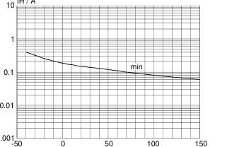
Tj / C
Fig.8. Minimum holding current as a function of
temperature.
Page 4
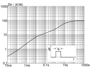
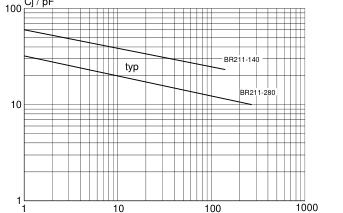
VD / V
tp / s
Fig.9. Typical junction capacitance as a function of
Fig.10. Transient thermal impedance. Zthj-a = f(tp).
off-state voltage, f = 1 MHz; Tj = 25˚C.
Page 5
MECHANICAL DATA
Dimensions in mm
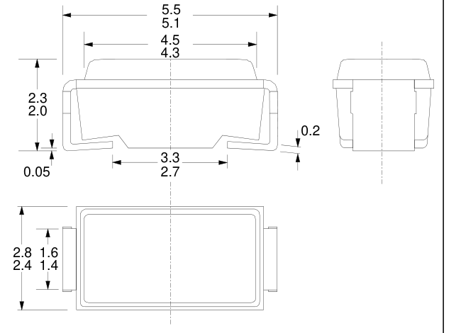
Net Mass: 0.2 g
Fig.11. SOD106.
Notes 1. For mounting and soldering instructions refer to publication SC18 "SMD Footprint Design and Soldering Guidelines". Order code:9397 750 00505.
Page 6
DEFINITIONS
Data sheet status Objective specification This data sheet contains target or goal specifications for product development. Preliminary specification This data sheet contains preliminary data; supplementary data may be published later.
This data sheet contains final product specifications.
Product specification Limiting values Limiting values are given in accordance with the Absolute Maximum Rating System (IEC 134). Stress above one or more of the limiting values may cause permanent damage to the device. These are stress ratings only and operation of the device at these or at any other conditions above those given in the Characteristics sections of this specification is not implied. Exposure to limiting values for extended periods may affect device reliability. Application information Where application information is given, it is advisory and does not form part of the specification. Philips Electronics N.V. 1996 All rights are reserved. Reproduction in whole or in part is prohibited without the prior written consent of the
copyright owner. The information presented in this document does not form part of any quotation or contract, it is believed to be accurate and reliable and may be changed without notice. No liability will be accepted by the publisher for any consequence of its use. Publication thereof does not convey nor imply any license under patent or other industrial or intellectual property rights.
LIFE SUPPORT APPLICATIONS
These products are not designed for use in life support appliances, devices or systems where malfunction of these products can be reasonably expected to result in personal injury. Philips customers using or selling these products for use in such applications do so at their own risk and agree to fully indemnify Philips for any damages resulting from such improper use or sale.