


 Download PDF
BMXCPS3540T SCHNEIDER
Document overview
- PDF pages: 6
Technical content
Page 1
Specifications
power supply module X80 - 125 V
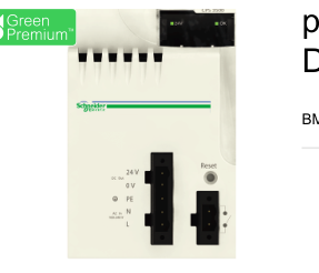
DC - for extended temperature
Main
Modicon X80
Range of product
Power supply module
Product or component type
Not compatible with BMEXBP..02
Backplane compatibility
Extended temperature
Product specific application
125 V
Primary voltage
DC
Supply circuit type
15 W 3.3 V DC I/O module logic power supply
Secondary power
31.2 W 24 V DC I/O module power supply and processor
Complementary
100...150 V
Primary voltage limit
350 mA 125 V
Input current
30 A 125 V
Inrush current
2 A².s 125 V
I²t on activation
0.05 A.s 125 V
It on activation
Internal fuse not accessible for primary circuit
Protection type
Overload protection for secondary circuit, 24 V sensor power supply Overvoltage protection for secondary circuit, 24 V sensor power supply Short-circuit protection for secondary circuit, 24 V sensor power supply
1.3 A 24 V DC I/O module power supply and processor
Current at secondary voltage
4.5 A 3.3 V DC I/O module logic power supply
8.5 W
Maximum power dissipation in W
1 LED (green)rack voltage OK
Status LED
1 LED (green)sensor voltage
RESET push-button cold restart
Control type
1 connector 2 pin(s)alarm relay
Electrical connection
1 connector 5 pin(s)line supply, protective earth, 24 V DC input sensor
= 100 MOhm primary/ground
Insulation resistance
= 100 MOhm primary/secondary
0.36 kg
Net weight
Environment
1 ms
Immunity to microbreaks
2000 V primary/secondary I/O module logic power supply
Dielectric strength

Page 2
500 V 24 V sensor output/ground
3 gn
Vibration resistance
30 gn
Shock resistance
IP20
IP degree of protection
2014/35/EU - low voltage directive
Directives
2014/30/EU - electromagnetic compatibility
Gas resistant class Gx
Environmental characteristic
Gas resistant class 3C4 Dust resistant class 3S4 Sand resistant class 3S4 Salt resistant level 2 Mold growth resistant class 3B2 Fungal spore resistant class 3B2
-40…85 °C
Ambient air temperature for storage
-25…70 °C
Ambient air temperature for operation
5…95 % at 55 °C without condensation
Relative humidity
Conformal coating
Protective treatment
0...2000 m
Operating altitude
2000...5000 m with derating factor
Packing Units
PCE
Unit Type of Package 1
1
Number of Units in Package 1
480.0 g
Package 1 Weight
13.7 cm
Package 1 Height
15.7 cm
Package 1 width
15.7 cm
Package 1 Length
S04
Unit Type of Package 2
12
Number of Units in Package 2
6.463 kg
Package 2 Weight
30 cm
Package 2 Height
40 cm
Package 2 width
60 cm
Package 2 Length
PAL
Unit Type of Package 3
48
Number of Units in Package 3
41.568 kg
Package 3 Weight
60 cm
Package 3 Height
80 cm
Package 3 width
48 cm
Package 3 Length
Offer Sustainability
Green Premium product
Sustainable offer status
REACh Regulation
REACh Declaration
Pro-active compliance (Product out of EU RoHS legal scope)
EU RoHS Directive
EU RoHS Declaration
Yes
Mercury free
RoHS exemption information
Yes
Page 3
China RoHS Regulation
China RoHS declaration
Environmental Disclosure
Product Environmental Profile
Circularity Profile
End of Life Information
The product must be disposed on European Union markets following specific waste collection and
WEEE
never end up in rubbish bins
WARNING: This product can expose you to chemicals including: Lead and lead compounds, which is
California proposition 65
known to the State of California to cause cancer and birth defects or other reproductive harm. For more information go to www.P65Warnings.ca.gov
Contractual warranty
18 months
Warranty
Page 4
Dimensions Drawings
Modules Mounted on Racks
Dimensions
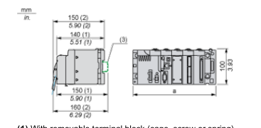
(1) With removable terminal block (cage, screw or spring). (2) With FCN connector. (3) On AM1 ED rail: 35 mm wide, 15 mm deep. Only possible with BMXXBP0400/0400H/0600/0600H/0800/0800H rack.
| Rack references | a in mm | a in in. |
| BMXXBP0400 and BMXXBP0400H | 242.4 | 09.54 |
| BMXXBP0600 and BMXXBP0600H | 307.6 | 12.11 |
| BMXXBP0800 and BMXXBP0800H | 372.8 | 14.68 |
| BMXXBP1200 and BMXXBP1200H | 503.2 | 19.81 |
Page 5
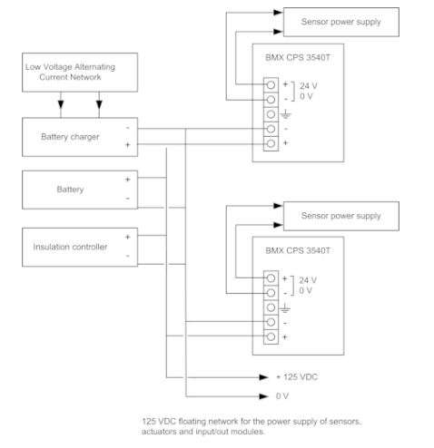
Connections and Schema
Connection of Direct Current Power Supply Modules to a 125 VDC Floating Direct Current Network
Page 6
Connections and Schema
Connection of Direct Current Power Supply Modules to an Alternating Current Network
Connection of a Single Rack PLC Station
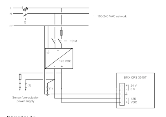
Q General isolator KM Line contactor or circuit breaker (1) Insulation connector bar for grounding
Connection of a Multi-Rack PLC Station
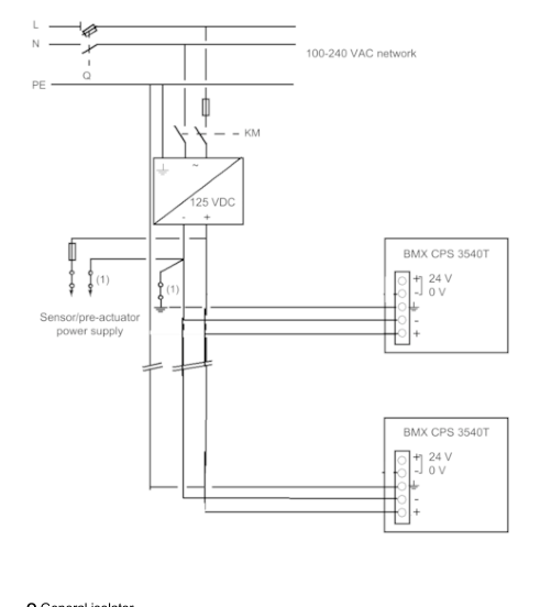
Q General isolator KM Line contactor or circuit breaker 1 Insulation connector bar for grounding