

 Download PDF
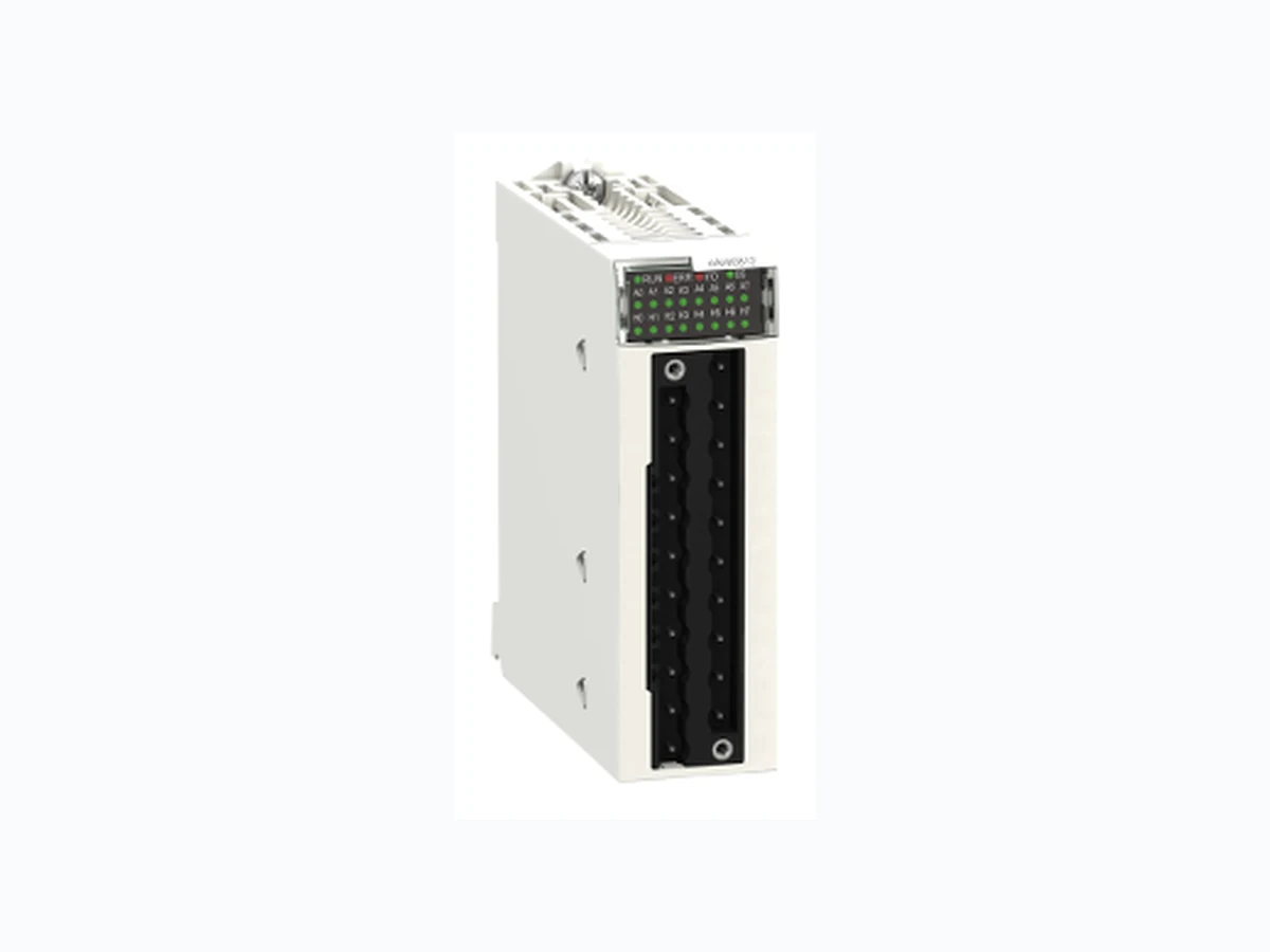
BMEAHI0812 SCHNEIDER
Document overview
- PDF pages: 6
Technical content
Page 1
Specifications
analog input module X80 - 8 inputs
HART - current Isolated
Main
Modicon X80
Range of product
Analog input module
Product or component type
Complementary
HART
Application specific I/O
BMEP58... processor
Product compatibility
BMXFTB20... terminal block ABE7CPA31 BMEXBP... backplane ABE7CPA02 ABE7CPA03 Head module BMECRA31210
20 ways terminal block
Electrical connection
Telefast
Isolated
Isolation between channels
8
Analogue input number
Current 4...20 mA
Analogue input type
15 bits + sign
Analogue input resolution
250 Ohm internally protective resistor (3.6 to 50 Ohm)
Input impedance
0.15 % of full scale 25 °C
Measurement error
<= 0.3 % of full scale 0...60 °C
50 ppm/°C
Temperature drift
1000 V DC for 60 s between channels
Isolation voltage
1400 V DC for 60 s between channels and ground 1400 V DC for 60 s between channels and bus
Broken wire detection
Checks
Point-to-point
Topology
I/O mapping
Function available
0.233 kg
Net weight
Environment
0…60 °C
Ambient air temperature for operation
2014/35/EU - low voltage directive
Directives
2014/30/EU - electromagnetic compatibility
CE
Product certifications
RCM

Page 2
CSA EAC Merchant Navy UL
EN/IEC 61010-2-201
Standards
EN/IEC 61131-2 UL 61010-2-201 CSA C22.2 No 61010-2-201
IP20
IP degree of protection
Packing Units
PCE
Unit Type of Package 1
1
Number of Units in Package 1
235.0 g
Package 1 Weight
5.5 cm
Package 1 Height
11 cm
Package 1 width
12 cm
Package 1 Length
S02
Unit Type of Package 2
15
Number of Units in Package 2
3.77 kg
Package 2 Weight
15 cm
Package 2 Height
30 cm
Package 2 width
40 cm
Package 2 Length
Offer Sustainability
Green Premium product
Sustainable offer status
REACh Regulation
REACh Declaration
Yes
REACh free of SVHC
Pro-active compliance (Product out of EU RoHS legal scope)
EU RoHS Directive
EU RoHS Declaration
Yes
Mercury free
RoHS exemption information
Yes
China RoHS Regulation
China RoHS declaration
Environmental Disclosure
Product Environmental Profile
Circularity Profile
End of Life Information
The product must be disposed on European Union markets following specific waste collection and
WEEE
never end up in rubbish bins
WARNING: This product can expose you to chemicals including: Lead and lead compounds, which is
California proposition 65
known to the State of California to cause cancer and birth defects or other reproductive harm. For more information go to www.P65Warnings.ca.gov
Page 3
Dimensions Drawings
Modules Mounted on Racks
Dimensions
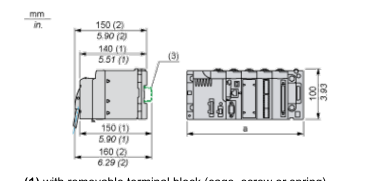
(1) with removable terminal block (cage, screw or spring) (2) with FCN connector (3) on AM1 ED rail: 35 mm wide, 15 mm deep. Only possible with BMEXBP0400/0400H/0800/0800H/1200/1200H rack.
| a (in mm) | a (in in.) | |
| BMEXBP0400 and BMEXBP0400H | 242.4 | 09.54 |
| BMEXBP0800 and BMEXBP0800H | 372.8 | 14.68 |
| BMEXBP1200 and BMEXBP1200H | 503.2 | 19.81 |
Page 4
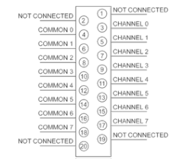
Connections and Schema
Module Connection
Page 5
Connections and Schema
Input Circuit Diagram
With 2-Wire Transmitter
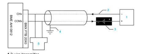
1 2-wire transmitter 2 4-20 mA current loop, with arrows indicating direction of current flow 3 Field power supply 4 Protective ground 5 Secondary HART master (hand-held)
With 4-Wire Transmitter
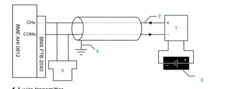
1 4-wire transmitter 2 4-20 mA current loop, with arrows indicating direction of current flow 3 Field power supply 4 Protective ground 5 Secondary HART master (hand-held)
With 2-Wire Transmitter and TELEFAST Connector with Power Supply
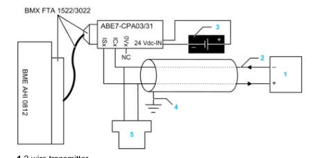
1 2-wire transmitter 2 4-20 mA current loop, with arrows indicating direction of current flow 3 24 Vdc power supply 4 Protective ground 5 Secondary HART master (hand-held)
With 4-Wire Transmitter and TELEFAST Connector with Power Supply
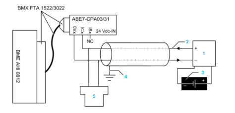
Page 6
1 4-wire transmitter 2 4-20 mA current loop, with arrows indicating direction of current flow 3 Field power supply 4 Protective ground 5 Secondary HART master (hand-held)
With 2-Wire Transmitter and TELEFAST Connector without Power Supply
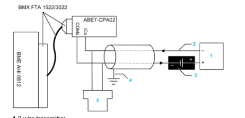
1 2-wire transmitter 2 4-20 mA current loop, with arrows indicating direction of current flow 3 Field power supply 4 Protective ground 5 Secondary HART master (hand-held)
With 4-Wire Transmitter and TELEFAST Connector without Power Supply
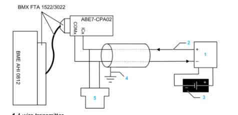
1 4-wire transmitter 2 4-20 mA current loop, with arrows indicating direction of current flow 3 Field power supply 4 Protective ground 5 Secondary HART master (hand-held)