
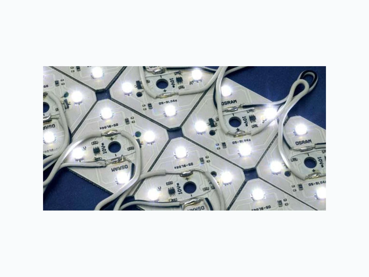
BL04L-W3F-865 OSRAM
Document overview
- Manufacturer or author: Provided By www.digicamel.com(FREE DATASHEET DOWNLOAD SITE)
- PDF pages: 4
Technical content
!!! Benefits One reel comes with two LED chains¾ For any shape of channel letter¾ Outstanding uniformity¾ Easy and fast installation¾ One reel for one OT 50W¾
Applications
Illuminated signs¾ Channel letters¾ Color Voltage [V DC]* Power [W]* Radiance Angle [°]* Wavelength [nm] Color Temp [K]* Lum. Flux [lm]* Current [A]* Product Number of LEDs Technical Operating Data white 10 44,0 120 6500 K 880 4,2BL04L-W3F-865 240 white 10 38,0 120 6500 K 510 3,6BL04S-W2-865 240 white 10 38,0 120 5400 K 510 3,6BL04S-W2-854 240 green 10 32,0 120 525 nm 430 3BL04S-T2 240 blue 10 32,0 120 470 nm 100 3BL04S-B1 240 All Data are related to the entire module Due to the special conditions of the manufacturing processes of LED the typical data of technical parameters can only reflect s tatistical figures and do not necessarily correspond to the actual parameters of each single product which could differ from the typical data. +) Preliminary Data Technical Features One reel comes with two LED-chains¾ One chain consists of 30 LED coupons connected with flexible cables Four LED per single printed circuit board¾ Total length for BL04S-version is max. 2 x 2,4 m = 4,8 m Cut into operable subunits at regular intervals¾ Mounting hole (Ø 4 mm) allows easy installation with screws or standard circuit board support hardware Parallel connection up to two LED chains with power feed in the centre of one OT 50W Only parallel connection allowed¾ Conformal coating protects against condensation water Page 1 of 4BL04 - 20.12.2007
Drawing is missing !!! Operating Temperature at Tc-Point [ °C ] * Storage Temperature [ °C ] * Product Voltage Range [ V dc ] * Reverse Voltage [ V dc ] * Minimum and Maximum Ratings Exceeding maximum ratings for operating and storage temperature will reduce expected life time or destroy the LED Module. Exceeding maximum ratings for operating voltage will cause hazardous overload and will likely destroy the LED Module. The temperature of the LED module must be measured at the Tc-point according to EN60598-1 in a thermally constant status with a temperature sensor or a temperature sensitive label. For exact location of the Tc-point see drawing below. Page 2 of 4BL04 - 20.12.2007
The LED module itself and all its components must not be mechanically stressed.¾ Assembly must not damage or destroy conducting paths on the circuit board.¾ ¾ To avoid mechanical damage to the connecting cables, the boards should be attached securely to the intended substrate. Heavy vibration should be avoided. Parallel connection is highly recommended as safe electrical operation mode. Serial connection is not recommended. Unbalanced voltage drop can cause hazardous overload and damage the LED module. Observe correct electrical polarity! For all W3 / W3F types (except LM10P / LD06A / DC02A) wrong polarity will lead to emission of red light. Attention, the module can be destroyed! Correct polarity immediately! For all other types, including LM10P / LD06A / DC02A), wrong polarity will lead to no light emission only (see also reverse voltage, page 2) ¾ Detach each circuit board unit of the LED-chain exclusively by cutting the connecting cables. ¾ Electrical contact is achieved with the contact cables. A maximum of one LED-chain can be installed with power feed from one end. Operation with more than one consecutive LED-chain, power feed from one end only, will reduce photometric performance and exceed the current carrying capacity of the LED-chains. ¾ Installation with more than one LED-chain on one OPTOTRONIC® 50W has to be realised by either feeding the power to the centre or by splitting the power feed to contact groups of single LED-chains. ¾ When using power supplies other than OPTOTRONIC® the maximum number of LED-chains on one 50 W power supply is: 2 for white and 2,4 for blue and green. Otherwise overloading may occur. ¾ The LED-chain can typically survive transient current levels of up to 3 Amperes. As a general design precaution, if the maximum output current of the power supply is more than 3 Amperes, fast-blow fuses should be incorporated into the wiring plan. ¾ If BL04 and OPTOTRONIC® class 1 power supply (e.g. OT50E) is being assembled on a metal grounded surface, use plastic screws or plastic connectors to fix BL04. Otherwise the LED-system does not fulfil SELV requirements. ¾ The module itself is protected against condensation water with a polymeric conformal coating. Supplementary soldering on any solder pad will destroy the conformal coating and with it protection against condensation water. ¾ If the IP rating of the fixture or channel letter system is required to be higher than IP22 the design of the housing should be according to the IP standards. Operation in or under water is not allowed. Installation of LED modules (with power supplies) needs to be made with regard to all applicable electrical and safety standards. Only qualified personnel should be allowed to perform installations. The LED Module incorporates no protection against short circuits, overload or overheating. Therefore it is absolutely necessary to operate the modules with a electronically stabilised power supply offering protection against the above mentioned safety risks. For dimming applications attention should be paid to specific references in "OPTOTRONIC ® Technical Guide". OSRAM OPTOTRONIC ® power supplies are specifically designed with protection features for safe operation. When using power supplies other than OPTOTRONIC ® the following basic safety features are required, in addition to any other application specific concerns and local safety codes: Short circuit protection¾ Overload protection Overheat protection Page 3 of 4BL04 - 20.12.2007
¾ Mounting of the LED-chain may be performed with screws or snap-in spacer (e.g. from Richco www.richco-int.com) by using Ø 4 mm holes in the circuit board. ¾ The mounting of the LED-chain is carried out by attaching it at the mounting holes. Mounting screws should be treated with synthetic washers to prevent circuit board damage and possible short circuiting. ¾ To connect the LED-chain with each other or with OPTOTRONIC® Power Supply we recommend standard clamps. (e.g. WAGO 243-214 or 224-201) Productgroup Productname EAN * S-Unit * Ordering Guide BACKlight 2G BL04L-W3F-865 4008321214706 5 BACKlight 2G BL04S-W2-865 4008321907370 5 BACKlight 2G BL04S-W2-854 4008321907356 5 BACKlight 2G BL04S-T2 4008321907318 5 BACKlight 2G BL04S-B1 4008321907332 5 EAN: Ordering number per single module S-Unit: Modules per shipping unit Note: Typical performance data are subject to change without any further notice, particularly as LED technology evolves. Related and Further Information OPTOTRONIC® Data Sheets¾ http://catalog.myosram.com OPTOTRONIC® Technical Guide¾ 130 T008 GB New creativity in lighting design LED Modules for illuminated signs ¾ 138 W002 GB Sales and Technical Support Sales and technical support is given by the local OSRAM subsidiaries. On our world wide homepage all OSRAM subsidiaries are listed with complete address and phone numbers. OSRAM GmbH Hellabrunner Strasse 1 D - 81536 München Germany www.osram.com +49 (0)89 6213-0 Page 4 of 4BL04 - 20.12.2007